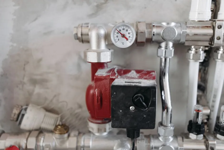
Industrial relay installation begins with isolation, then proceeds through wiring, mounting, functional testing, and acceptance checks.
For panel and UPS applications, verify coil voltage, contact capacity, conductor size, and fault behavior before returning the circuit to service.
Relay Types and Selection Criteria
Electromagnetic relays use an energized coil to move contacts, solid-state relays switch through semiconductor devices, reed relays use contacts sealed in glass, and magnetic-latching relays retain their state after coil power is removed [S1]. These construction differences determine switching behavior, isolation, load suitability, and the commissioning checks required for an industrial relay.
For an electromagnetic relay, begin with coil voltage. Catalog examples include a 12 V AC, 11-pin relay with an included DIN socket and a 48 V DC, 11-pin version [S3][S4]. For the 48 V DC model, the stated contact capacity is 10 A at 250 V AC, with an arc suppressor recommended for inductive loads [S4]. Do not transfer that rating directly to every load: confirm the exact model, load category, switching voltage, and current.
The Eaton Industrial Relay Card (IRC) indicates the operating status of the UPS system using the customer's monitoring equipment.
This comparison favors an electromagnetic relay for conventional control circuits, an SSR when switching frequency or semiconductor control is required, a reed relay for suitable low-level signals, a magnetic-latching relay when state must survive power loss, and a status card when the required output is isolated UPS-condition reporting [S1][S2].
Isolation, Mounting, and Wire Preparation
For the Eaton IRC, verify that the UPS is off and that all power sources are removed before installation [S2]. The same basic sequence applies to field relays: disconnect the source, make the circuit safe to work on, and verify isolation before removing covers or handling terminals [S1].
Mount a plug-in industrial relay on its DIN-rail socket where the relay body inserts into the socket and the socket is secured to the panel rail with screws [S3]. Prepare conductors for the manufacturer-specified terminals, maintain insulation at the required clearance, and prevent loose strands from bridging adjacent terminals. The IRC procedure specifies 1/2-inch conduit for wiring between the card and customer monitoring equipment [S2].
Connect wiring between the IRC plug-in terminal block J2 and the customer's monitoring equipment using the terminations shown in Table 1.
Confirm each coil terminal against the 12 V AC or 48 V DC control supply for the selected catalog relay [S3][S4]. A relay selected for 48 V DC should not be connected to a 12 V AC source merely because the socket geometry appears compatible. Socket compatibility does not establish electrical compatibility.
Wiring Failures: Symptom, Cause, and Correction
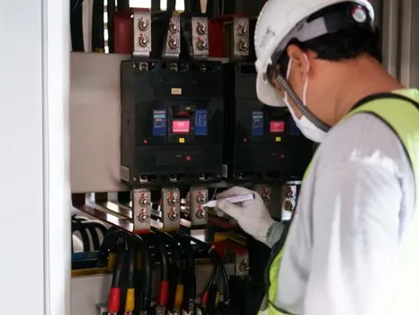
A relay that does not activate is commonly caused by incorrect coil voltage, an open circuit, or a loose terminal; correct the supply and connections, then measure voltage at the coil [S1]. If the relay still fails to pick up after coil voltage and wiring are confirmed, replace it only after the underlying circuit fault is removed. Continuing to cycle an underpowered coil creates avoidable contact and heat damage.
A relay that operates but leaves the load off usually indicates incorrect NC or NO wiring, a wrong common connection, or a control command that is not reaching the field device. Verify the intended contact state against the actual load state, then operate the field input manually. Do not swap NO and NC on the assumption that all relays use one convention; the IRC assigns separate numbered points for each state [S2].
A relay that repeatedly clicks can indicate coil chatter, mechanical contact bounce, or an unstable command. Check contact cleanliness and debris where accessible, but do not use solvents or aggressive contact cleaners unless the relay manufacturer permits them [S1].
Before installing the IRC, verify that the UPS system is turned off and all power sources are removed.
Heat, Inductive Loads, and Contact Damage
Excessive heat indicates excessive current, restricted cooling, unsuitable load duty, or contact damage. Check the actual load current against the selected relay rating and verify that the relay is mounted with adequate ventilation [S1]. The 48 V DC, 11-pin catalog relay is rated up to 10 A at 250 V AC, but the manufacturer specifically recommends an arc suppressor for inductive loads [S4].
Do not use the 10 A value as a blanket continuous-duty rating. It identifies the stated maximum contact current for that model and voltage; an inductive or DC load can impose different arcing and interruption conditions.
Contactor installation has different sizing and mechanical concerns, so use a contactor where the load requires an industrial contactor rather than a relay package. For relay panels, inspect for discoloration, melted insulation, loose lugs, or damaged contact surfaces. Replace a relay with known contact damage instead of merely reconnecting it. De-energize and isolate the circuit before removing damaged hardware.
When an inductive load cannot be changed, apply the protection method specified by the relay or load manufacturer. The 48 V DC relay documentation explicitly identifies an arc suppressor as recommended, but it does not specify a suppressor part number or value in the supplied material [S4]. Select that component from the load manufacturer’s switching data rather than inventing a generic RC or diode network.
Commissioning Tests and Acceptance Criteria
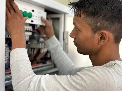
Before energizing, perform a visual inspection of relay model, coil voltage, terminal assignments, conductor size, socket retention, insulation, and mechanical clearance. The Eaton procedure uses wire range 16–24 AWG for the IRC and identifies J2-1 through J2-12 as the complete termination set [S2]. Confirm that the installed conductors fall within that range and that each lands on the assigned terminal.
Energize the control circuit in a controlled sequence. Measure voltage across the relay coil and confirm that it matches the nameplate value for the selected device, including 12 V AC or 48 V DC examples [S3][S4]. For the Eaton IRC, operate the UPS through inverter or bypass and verify that the customer monitoring equipment displays the corresponding status [S2].
Exercise all four Eaton status paths: normal, bypass, alarm, and battery mode. Confirm that the appropriate NC or NO indication changes and that no unintended contact changes state [S2]. If status is incorrect, inspect wiring, the IRC fuse, and J2 terminal seating in that order; replace the fuse only if all wiring and seating checks pass and operation remains abnormal [S2].
For an electromagnetic relay, perform a functional load test after the no-load state check. Confirm coil operation, intended contact transfer, load response, and absence of abnormal heating. A relay can energize correctly yet still fail under load because of an incorrect contact rating, loose conductor, insufficient ventilation, or unsuitable switching duty [S1].
Application Fit, Limitations, and Service Decisions
Install relays in control, interlock, status, and automation circuits where the coil and contact specifications fit the load. Do not select a relay solely by pin count or socket shape. The two catalog relays both use 11 pins, yet their coil supplies differ at 12 V AC and 48 V DC [S3][S4].
Reed relays are suited to their limited low-level contact duty, while SSRs require attention to semiconductor switching and heat dissipation [S1]. Magnetic-latching relays suit applications requiring memory, but their retention behavior must be tested against the required set and reset sequence [S1]. None of these constructions removes the need to verify the manufacturer’s load ratings.
Replace rather than repair a relay with damaged insulation, visibly burned contacts, melted housing, or heat damage that cannot be traced and corrected. Escalate equipment-specific failures to authorized service personnel, particularly for UPS relay cards whose manufacturer documentation states that the card is not user-serviceable [S2]. Record the relay model, coil voltage, load rating, test date, measured coil voltage, and observed contact state in the commissioning file.