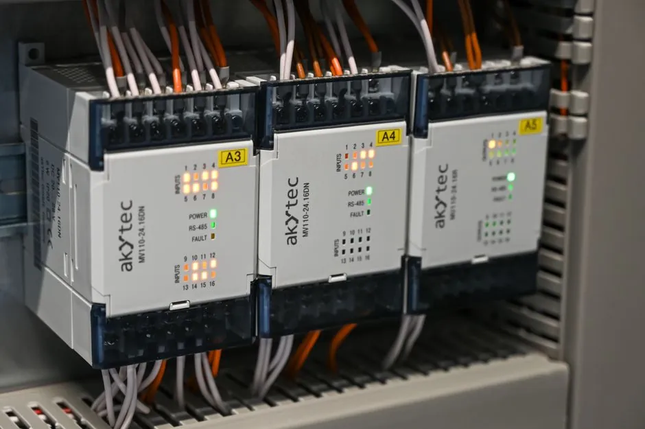
Install a fieldbus gateway on DIN rail, verify its power and wiring, configure the protocol mapping, and commission it with segment diagnostics before connecting production equipment.
The procedure applies to the SEW-EURODRIVE UFF41B fieldbus gateway for DeviceNet and PROFIBUS DP [S1].
Choose the gateway topology before mounting
A fieldbus gateway is appropriate when a control system needs to translate between a fieldbus segment and another protocol, expose field data to an Ethernet or cloud service, or isolate legacy equipment from a new controller [S2][S3].
The gateway is not a substitute for a correctly engineered fieldbus network. It is intended for installations where the fieldbus, electrical interface, enclosure, and upstream network have been designed for their operating environment. FOUNDATION fieldbus wiring guidance covers 31.25 kbit/s voltage-mode networks, including topology, spurs, repeaters, cable mixing, shielding, polarity, and DC power for two-wire devices [S4].
The imp005-based design is a different class of product. The impAccelerator Fieldbus Gateway can support isolated Modbus RTU (RS-485) or Modbus TCP (Ethernet) devices or subsystems [S3]. Selection should therefore begin with the required protocol and electrical interface, not with enclosure size or cloud connectivity.
Mount the gateway and establish its power
Mount the gateway on a DIN rail inside the specified enclosure, maintain the required cable routing and separation from power conductors, and secure the wiring before energizing the device [S1][S2]. For FOUNDATION fieldbus, the gateway belongs within the fieldbus segment, and its installation must preserve the segment design defined for 31.25 kbit/s voltage-mode wiring [S2][S4].
Check the supply before inserting fieldbus wiring. The UFF41B manual identifies separate voltage-supply arrangements for installation in the MOVIAXIS master module and the UOH21B gateway housing, so the gateway should be powered from the arrangement specified for the chosen housing rather than from an unverified auxiliary source [S1].
Record the gateway name, serial number, firmware or software version, protocol, IP address, and DIP-switch position before startup. The UFF41B documentation includes a DIP switch S1 that defines a default IP address, making the physical switch position part of the commissioning record [S1].
Terminate fieldbus wiring and verify polarity

For FOUNDATION fieldbus, verify the segment topology, cable type, shield or screen treatment, polarity, and DC power path before attaching the gateway to production devices [S4]. The installation guide identifies polarity and DC power for two-wire devices as separate design checks, so a powered but reversed connection should not be accepted merely because the gateway indicator illuminates [S4].
For PROFIBUS DP and DeviceNet installations, follow the gateway-specific terminal assignments rather than a generic fieldbus diagram. The UFF41B identifies CAN system-bus connectors X33 and X32, an SBUS plus system-bus terminal X36, and engineering Ethernet terminal X37, with a dedicated pin assignment for X37 [S1].
Use shielded cable where required by the bus design, terminate the cable in the prescribed manner, and verify continuity or absence of shorts before power-up. FOUNDATION guidance covers mixing cables and shielding as distinct installation considerations [S4]. Do not substitute the RS-485 wiring rules used by Modbus RTU for a PROFIBUS DP, DeviceNet, or FOUNDATION segment, because these are different physical-layer systems.
Configure protocol mapping and network addresses
Configure the gateway in the order required by its product documentation: physical network, protocol role, device addresses, data map, network parameters, and upstream interface. A FOUNDATION fieldbus to Modbus gateway installation involves mounting the gateway within the FF segment and then following the product's step-by-step configuration procedure [S2].
The programmable Electric Imp impAccelerator Fieldbus Gateway is based on the imp005 module and provides a customizable platform for fieldbus-to-cloud connectivity [S3]. The impAccelerator Fieldbus Gateway can support isolated Modbus RTU over RS-485 and Modbus TCP over Ethernet [S3].
Set every fieldbus address and Modbus register or data point from the approved engineering database, then record the mapping in the commissioning dossier. For a cloud-connected design, configure Internet connectivity through the Fieldbus Gateway Getting Started Guide and review the impCloud security model before exposing live process values [S3].
Diagnose startup failures by symptom and root cause

If the gateway has no status indication, check the supply selection, wiring, connector seating, and the applicable housing arrangement before replacing the unit. The UFF41B provides a status LED and separates power, CAN, SBUS, and Ethernet connections into distinct installation sections, allowing a point-of-test diagnosis rather than blind module replacement [S1].
If the status LED operates but the fieldbus will not enumerate, inspect polarity, cable continuity, shields, termination, addresses, and segment topology [S4]. If the gateway is reachable by Ethernet but Modbus or field data is absent, inspect the protocol map, register addresses, device descriptions, and upstream network settings. The FOUNDATION-to-Modbus workflow separates physical installation from configuration, which makes an addressing or mapping error more likely than a physical failure [S2].
Replace or escalate the gateway when the supply and terminations meet the product specification but the fault remains, when the device has physical damage, or when its status indicators show an internal fault. Do not adjust the protocol map as a substitute for correcting wiring, because an incorrect mapping can conceal a failed field device or create an unsafe control command.
Compare gateway classes before commissioning
A fixed protocol gateway is the practical choice for a stable conversion such as FOUNDATION fieldbus to Modbus. It is configured around one defined installation workflow and mounted within the FF segment [S2]. A programmable gateway is more flexible for Modbus RTU, Modbus TCP, BACnet, USB, UART, and custom applications, but requires application development and a deliberate security design [S3].
The UFF41B is a fixed-purpose drive-system gateway for DeviceNet and PROFIBUS DP, with model-specific terminals X32, X33, X36, and X37 and a defined DIP-switch default IP address [S1]. In comparison, the imp005 platform accepts 8–24 V AC/DC, isolated Class 2 PoE, or 5 VDC power, and exposes dual-band 2.4 GHz and 5 GHz 802.11abgn WiFi plus two Ethernet connectors [S3].
For hazardous installations, use an application-specific engineering guide and the applicable certification requirements for the exact device and area. The Pepperl+Fuchs Fieldbus Engineer's Guide addresses different hazardous-area applications, applicable standards, and general installation notes, while FOUNDATION fieldbus H1 documentation identifies protection methods accepted for potentially explosive atmospheres [S5][S7].
Complete commissioning with documented acceptance tests
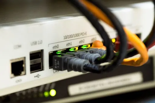
Commission from an isolated or controlled test condition, verify each physical connection, then test protocol exchange with known values before enabling control outputs. The acceptance record should include the gateway configuration, fieldbus addresses, protocol map, supply arrangement, software version, indicator states, and test results [S1][S2].
For FOUNDATION fieldbus, validate against the 31.25 kbit/s application guidance covering topology, spurs, repeaters, mixed cable, shielding, polarity, and device power [S4]. Confirm that the installed segment remains within the intended design rather than relying only on a successful connection test. The Fieldbus Foundation system-engineering downloads provide additional installation and design references [S6].
For the UFF41B, verify the engineering Ethernet connection through X37, confirm the configured default IP address against DIP switch S1, and inspect the gateway status LED before testing DeviceNet or PROFIBUS DP traffic [S1]. For an imp005 design, test WAN Ethernet, isolated LAN Ethernet, RS-485 isolation and transmit inhibit, and any enabled USB, MikroBUS, or XBee interface [S3].
Commissioning is complete only when the gateway is stable under the intended communication load, mapped values agree with field measurements, fault conditions produce the required alarm behavior, and the as-built configuration is stored with the installation record.