
Select an installation contactor rated for 16–100 A for modular DIN-rail switching of lighting, heating, ventilation, EV charging, motors and pumps, while checking the required load category and approvals [S1].
The ABB ESB installation contactors offer AC/DC coils and tool-free accessories, and the 36-page guide covers IEC-based local approvals and North American standards [S1].
Contactor function and application scope
A contactor is an electromechanical switching device used to connect or disconnect a load from a power circuit, commonly under a separate control circuit [S3]. Installation contactors are intended for switching and controlling lighting, heating, ventilation, EV charging stations, motors and pumps; the ABB ESB range spans 16–100 A [S1].
This guide is aimed at electricians, panel builders, maintenance technicians and facility personnel installing modular DIN-rail contactors. It is not a complete motor-starting design manual and does not cover every ABB motor-starting product [S1]. For motor starting, protection coordination, enclosure selection and branch-circuit design, use the applicable motor-starter data and local electrical code rather than treating an installation contactor as a complete starter.
The installation contactor family also offers hum-free AC/DC coils and tool-free accessories, which can reduce assembly effort in noise-sensitive installations [S1]. The contactor reference defines the broader device category, while the acceptance process must remain governed by the selected product, load and installation rules.
Selection criteria: voltage, current, poles and duty
Select a contactor based on voltage, current and applicable industry standards [S2].
Main contact ratings must cover the load, but motor starting current can exceed the motor's full-load current. The selected contactor must be approved for the relevant category, not merely for its nameplate current.
Do not use the generic ranges in the comparison table as a substitute for the manufacturer's product data.
Mounting and preparation
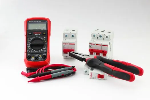
Mount the contactor on a suitable DIN rail or panel location with adequate accessibility and ventilation, using the specified fasteners and brackets. Before removing or installing a device, isolate the power, verify absence of voltage with an appropriate tester and label conductors for reconnection [S3].
The tool list includes screwdrivers, wire strippers, wire nuts and connectors, electrical tape, a circuit tester, a multimeter, safety gloves and goggles, and electrical wires [S3]. These items do not replace good electrical work practice: the same source recommends consulting a licensed electrician for electrical installation or modification when the installer lacks the required competence [S3].
Prepare the design information before mounting. It should include the load requirements, conductor sizes, control voltage, pole arrangement and required protective devices.
Check that the enclosure and selected protection suit the installation location, including the required ambient conditions and approvals. ABB's guide covers European directives, CE marking, North American standards, CCC certification, local approvals based on IEC standards and marine approvals, with the exact applicable document listed for each product [S1].
Power and control-circuit connection
Connect control conductors to the coil terminals and load conductors to the main terminals according to the product wiring diagram. A1 and A2 are coil terminals in the article's discussion of contactor wiring [S4].
Do not assume that every coil behaves identically. ABB identifies hum-free AC/DC coils within the ESB installation-contactors family [S1], but the exact coil voltage, frequency, consumption and inrush must come from the ordered product data. The industrial relay and circuit breaker references cover adjacent panel functions, not substitutes for the contactor's own overload and short-circuit coordination.
Mixed loads require particular restraint because the utilization categories above have different switching characteristics [S1].
Commissioning and acceptance tests
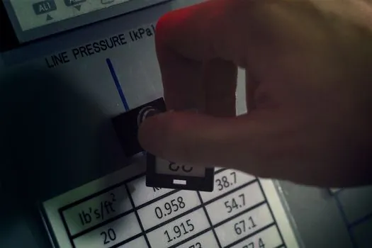
Commissioning begins with a visual inspection before energization: confirm correct mounting, secure terminals, adequate conductor spacing, correct protective-device ratings and complete closure of the enclosure [S3]. With the circuit isolated, verify continuity and insulation as required by the approved test plan. Then energize the control circuit first and confirm that the contactor pulls in, the auxiliary contacts change state and the main circuit behaves as designed.
Use a multimeter to verify control voltage and test that the contactor opens and closes when the control command is applied [S3]. Acceptance should include coil response, every intended switching state, operation of interlocks and auxiliary contacts, and observation for abnormal sound, smell or signs of overheating [S3].
For a motor load, an installation contactor alone does not provide complete overload protection. Coordinate the contactor, overload device, short-circuit protection and conductor ratings as a motor-starting assembly. The circuit breaker installation guide is relevant when the protective device is part of the same commissioning workflow.
If the coil fails to energize, first verify the isolated-power step, then compare the actual control voltage and frequency with the nameplate data, inspect A1/A2 connections and check for an interlock or control-circuit fuse. If the contactor pulls in but the load does not start, inspect main-terminal connections, upstream protection and the load itself. Replace the contactor if it shows mechanical damage, pitting, overheating or failed insulation; do not repair damaged mains poles with insulating tape [S3].
Maintenance, failure symptoms and escalation
Preventive inspection should check terminal tightness, contamination, abnormal heat, mechanical wear, coil noise and the condition of connected conductors. Clean only with methods approved for the equipment, and keep control circuits free of conductive dust and moisture [S2]. Re-torque terminals only when the product instruction sheet or maintenance procedure permits it, because some contact designs do not permit repeated tightening [S1].
For comparison, the ABB ESB range is available from 16–100 A and covers switching of lighting, heating, ventilation, EV charging, motors and pumps, but product suitability still depends on voltage, category and approvals [S1].
Use the manufacturer's product-specific instructions, ABB's 36-page installation guide and the applicable local code together [S1], and