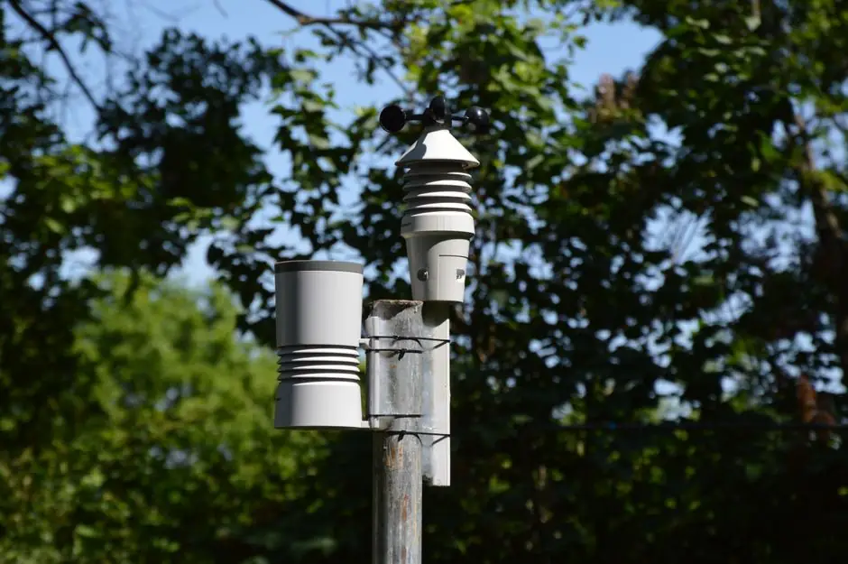
IO-Link enables cyclic exchange of digital process data and acyclic exchange of parameter and diagnostic data between a master and its associated devices.
Its point-to-point digital interface supports bidirectional sensor and actuator communication under IEC 61131-9, while field-level data can feed PLCs, industrial Ethernet, MES, ERP, or cloud systems [S2][S4].
What IO-Link Adds Beyond Conventional Sensor Signals
IO-Link uses a serial, bidirectional point-to-point connection to carry process data and supply power beneath a fieldbus, industrial Ethernet, or backplane architecture [S2][S4]. Unlike a conventional analog output, the link can exchange raw sensor values, diagnostic information, parameters, and device identification [S1][S4].
The practical difference is visible in multi-value devices. One IO-Link sensor can potentially replace several devices by supplying multiple process values over a single wire. An IO-Link master also provides the gateway between the field device and the higher-level automation network [S4].
Each IO-Link sensor has an IODD (IO Device Description) file that describes the device and its capabilities.
Selection Criteria for Sensor-Level Connectivity
IO-Link is most suitable when the specification requires more than a binary or analog process value, especially where diagnostics, parameter changes, or automatic sensor replacement can reduce maintenance effort [S1][S3]. The master supports cyclic digital input and output data plus acyclic parameter and diagnostic exchange [S4].
Connection requirements are defined at the physical interface.
That makes master-port design, connector rating, conductor count, and cable length first-order checks before choosing a sensor.
IO-Link, Analog IO, and Conventional Digital IO Compared

Traditional digital input and analog output wiring limits each sensor to the value carried by its physical channel. Analog signals are susceptible to noise, and repeated digital-to-analog conversions can degrade accuracy between collection and processing [S1]. IO-Link retains the conventional point-to-point connection while adding digital communication, device identification, and parameter access [S2][S4].
On communication depth, conventional digital IO carries switching status, IO-Link carries digital process data plus acyclic parameters and diagnostics, and analog IO carries a scaled process variable without IO-Link device services [S1][S4]. IO-Link field-mount devices can be connected mechanically, versus a labor-intensive wiring harness, and one IO-Link sensor can potentially supply multiple process values over a single wire.
On maintenance, IO-Link permits parameter reassignment when a device is replaced, remote parameterization from a controller or HMI, and point-of-issue diagnostics [S1][S4]. These functions are absent from basic point-to-point switching, so a simple standalone installation may not justify the added master and configuration infrastructure [S3].
Commissioning, Diagnostics, and Replacement Gains
Bidirectional communication lets engineers upload a configuration file, after which field modules and devices can be commissioned in seconds [S1]. Tool-supported parameter assignment and central data management reduce the need to configure each sensor manually [S4]. The same interface supports automatic parameter reassignment during device replacement and device verification after a part swap [S1].
Point-of-issue diagnostics link a fault to the affected field device rather than leaving the investigation at the cabinet level [S1][S4]. Consistent diagnostic information extends from the controller to the sensor or actuator, improving the data available for maintenance decisions [S4]. IO-Link-enabled systems also support remote accessibility and automated device communication, which can support condition monitoring and shorter troubleshooting paths [S7].
One ifm example states that IO-Link communication modules are field-ready and designed to reduce control-panel cabinet requirements, while its IO-Link architecture moves I/O into the field. These are vendor estimates, not universal performance guarantees, so project acceptance should use machine-specific wiring, labor, and downtime baselines.
Industrial Data Use Cases and System Boundaries
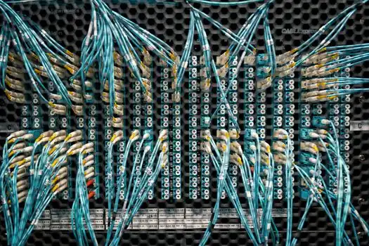
Sensor-level data supports immediate process action and long-term analysis through PLCs and HMIs, with the master able to place the data on networks leading to MES, ERP, or cloud systems [S3][S4]. That chain makes IO-Link a field-level data source for the Industrial Internet of Things, rather than a replacement for the control layer or a high-speed fieldbus [S2][S3].
Good candidates include flow installations that benefit from temperature and diagnostic data through one cable, changeover-heavy machines that benefit from remote recipe adjustment, and systems where failed sensors must be replaced without manual reconfiguration [S1][S3]. The same evidence supports maintenance systems that need more than a simple on/off state [S6].
IO-Link is not the right default for every sensor. Standalone equipment may already provide the required value and operational capability, while specialty sensors may not yet support IO-Link [S3]. The decision should be based on required data, diagnostics, parameterization, replacement workflow, and cabinet architecture, not on the installed-node count alone.
Standards and Interoperability Controls
IO-Link is defined by IEC 61131-9 as an open, point-to-point communication technology for sensors and actuators [S2][S3]. It is not a fieldbus, and its master can connect the device layer to fieldbus, industrial Ethernet, or device-specific backplane systems [S2][S4].
Interoperability depends on more than a physical connector. IODD files identify each device and describe its capabilities for system integration [S3][S4]. The IODDfinder service provides a non-proprietary central database for viewing and downloading manufacturer IODDs, while the configuration tool handles project engineering and parameterization [S4].
IO-Link profiles add a common method for describing compatible device data and behavior, supporting consistent implementation across products [S8]. Engineers should still verify the exact IODD, operating mode, process-data range, parameter set, and master compatibility. Port operating modes include IO-Link communication and standard I/O behavior when the connected device does not use the full IO-Link service set [S4].
Adoption Benefits Depend on the Data Use Case

IO-Link creates value when a project converts sensor-level parameters and diagnostics into faster commissioning, reduced cabinet wiring, remote configuration, and automatic replacement workflows [S1][S4]. The strongest business case combines measurable field data needs with IO-LINK masters, IODD-based engineering, and maintenance processes that can consume the added information [S3][S4].
Track the same evidence used for acceptance: field-device count, process values per device, cabinet terminals, commissioning hours, replacement recovery time, and diagnostic resolution [S1][S3]. A deployment plan for edge versus cloud analytics can then define which sensor data must be processed near the machine and which data can be retained for longer-term analysis.