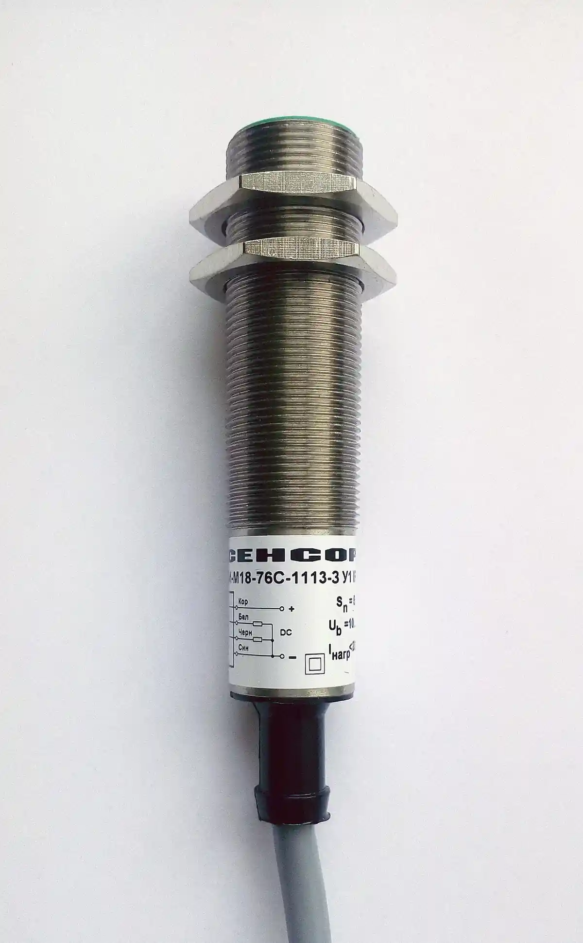
IO-Link is a point-to-point digital communication standard, IEC 61131-9, that connects one sensor or actuator to one port on an IO-Link master over ordinary three wire cable, the same unshielded cable analog devices have always used. The master's port talks to the device in cycles of a few milliseconds: process data, the measurement or state, streams continuously; parameter data reads and writes on demand; and diagnostics and identification travel the same single channel. A pressure sensor stops being a 4 to 20 mA loop with one number in it and becomes a named device on the network with a serial number, a calibration table, event flags, and readable health.
The technology occupies the space between discrete wiring and fieldbus. Below it, the traditional analog and switching signals: robust, cheap, and mute, one bit or one value with no identity and no dialogue. Above it, the fieldbus and industrial ethernet layer, EtherNet/IP, PROFINET, Modbus TCP and their kin, which carry hundreds of devices with rich data but demand engineered infrastructure. IO-Link is the last meter: it digitalizes the sensor conversation without touching the architecture above, because the master presents whatever protocol the controller already speaks on its uplink. The buyer's decisions are the master class and port count, the COM speed of the devices, the IODD device description management that makes devices interchangeable and configurable, and the integration of parameter storage and diagnostics into the maintenance practice of the plant.
This page treats IO-Link as a system purchase: how the point-to-point protocol layers process, parameter, and diagnostic data over the sensor wire; what master classes and COM speeds mean in delivery terms; how IODD files and parameter servers make device replacement a five minute job instead of a tuning session; how cable length, port current budgets, and data storage strategy are specified; and what an RFQ must state so the installed base talks to the controller it already has, in the language it already speaks.
Chapter 1 / 06
What IO-Link Is and What Is Being Decided
The physical layer is deliberately humble. One device, one port, one cable: three conductors, up to 20 m, M8 or M12 connectors, unshielded, carrying the 24 V supply and a switched communication signal in both directions. Port classes come in two letters that every RFQ uses: port class A, type A, with pins 1 and 3 as supply and pin 4 as the communication line, plus pin 2 free for auxiliary uses; and port class B, type B, which adds dedicated power pins for actuators with higher current draws, up to 2 A class, on the same connector family. Because the wire is ordinary and the connectors are the plant's existing standard, the retrofit cost is the master, not the infrastructure, and that is the economics the whole technology stands on.
What is being decided at purchase divides into four commitments. First, the master architecture: how many ports, which port classes, mounted where, field or cabinet, and with what uplink, because the master's uplink is the plant's existing protocol, and the choice of master family is largely the choice of ecosystem, PROFINET, EtherNet/IP, Modbus TCP, or the remote I/O it already owns. Second, the device fleet: which sensors and actuators ship as IO-Link versions, at which COM speed, and with which IODD quality, because a device without a usable IODD is a smart device that cannot be asked a question. Third, the data practice: parameter storage strategy, master side, server side, or neither, the maintenance workflows that use event and diagnostic flags, and the SCADA or MES consumption of the richer data. Fourth, the engineering discipline: port current budgets, cable length rules, configuration management of the IODD library, and the acceptance test that proves the parameter server works before the plant depends on it.
The standard's identity is IEC 61131-9, the ninth part of the programmable controller family that Parts 1 through 8 built. The system and interface specification maintained by the IO-Link consortium implements and extends it: the protocol stack details, the IODD specification, the system configuration rules, and the test specifications that devices and masters pass for interoperability certification. The buyer cites IEC 61131-9 for the standard anchor and the consortium specification version for implementation currency, and the certification marks on devices and masters are the interoperability evidence.
Within the automation landscape, the neighbor boundaries are clean. IO-Link is not a fieldbus: no multidrop, no multi device segments, one wire one device by design, and the collision free simplicity is exactly why it is cheap and deterministic. It does not replace the fieldbus or industrial ethernet uplink; it feeds it through the master. It does not compete with safety protocols: safety signals travel the standard architecture's dedicated channels, and an IO-Link device's process data is not a certified safety channel, though the ecosystem integrates safety sensors whose status reporting rides alongside. And it does not analogize away: a 4 to 20 mA loop still wins on cable runs beyond 20 m, on intrinsic safety in Ex areas, and on the sheer installed inertia of millions of analog inputs, which is why hybrid masters, ports configurable as IO-Link or analog, are the volume product.
Finally, what is being decided is maintenance economics as much as communication. The three features that pay the technology's way in most plants are device identification, the controller knows which serial number is on which port; remote parameter access, configuration reads and writes without a laptop at the sensor; and the parameter server, automatic re-provisioning of a replacement device from the master's stored parameter set. Together they convert a failed sensor swap from a commissioning event with a configuration printout into a five minute exchange, and the RFQ language in chapter 5 is mostly about locking those three features into the installed practice.
Chapter 2 / 06
How the Protocol Layers the Sensor Conversation
The conversation runs in fixed cycle telegrams. Each cycle, the master sends a downlink telegram and the device answers an uplink, each carrying a few bytes of process data plus protocol overhead. The three transfer types divide the payload: process data, cyclic, the measurement and status the control loop consumes, 0 to 32 bytes by device; parameter data, acyclic, on-demand reads and writes of the device's configuration and identification memory through the ISDU indexed service data unit channel; and page-type messages carrying events, diagnostics, and small flags. Cycle times run 2 ms per port at the fastest COM speed for short process data, scaling up with data length and down with speed, and the master's port scheduler serves its ports in rotation, so an 8 port master's aggregate throughput is the port count times the per port cycle arithmetic.
COM speeds are the three data rates a port negotiates with its device: COM1 at 4.8 kBd, the legacy and slowest, retained for compatibility with early devices; COM2 at 38.4 kBd, the volume standard; COM3 at 230.4 kBd, the fast tier for data hungry devices like encoders and measuring light curtains. The port falls back through the rates during wakeup, so mixed fleets coexist on one master, and the cycle time consequence of speed choice is direct: the same 2 bytes of process data cycle about 2 ms at COM3 and about 15 ms class at COM2, and a device with 16 bytes of data makes the user choose between speed and cycle budget explicitly. RFQ practice is to specify the fleet's dominant speed and accept the fallback rather than to demand COM3 of devices that do not offer it.
The data types structure the payload semantics. Process data arrives with a qualifier, the cycle counter and communication status bits that let the controller detect stale or invalid data rather than act on it silently. Value semantics come from the IODD, the device description file: an XML schema plus optional language and image assets that declares every parameter, its data type, allowed ranges, units, and the device's identification, vendor ID, device ID, and version. The IODD is what makes a device's 47 parameter index readable as "switching point, 5.5 mm, step 0.1" instead of raw hex, and the IODD checker tools and repositories are part of the ecosystem's plumbing. Devices with absent or broken IODDs still communicate, but the configuration experience collapses to index level hex, which is why IODD quality is a purchase criterion, not an afterthought.
Diagnostics ride the event channel with defined codes. Device events divide into application and system diagnostics, with error and warning severity, and the standard's diagnostic code table plus the IODD's text give each code a meaning the controller and the maintenance system can present in words: out of range, short circuit, contamination warning on an optical sensor, temperature, and the like. The practical payoff is triage without a multimeter: the fault arrives at the HMI as a sentence with a timestamp and a port address. Plants that consume these events in the CMMS convert the diagnostic channel into mean time to repair reduction, and the specification exercise is deciding that consumption in advance rather than discovering unread event logs after the first crisis.
Block parameterization and data storage close the protocol's service story. Parameter access supports single indices and block transfers for bulk operations, so a device's full configuration reads and writes in seconds. The data storage subsystem formalizes the parameter server: the master, or a management level above it, holds the last known parameter set per port, and on device replacement, with user confirmation policies by vendor, the set downloads automatically, with the event logged. Configuration management discipline still applies, vendor and device ID matching, version drift review, and a periodic export of parameter sets to the plant's configuration library, because a parameter server is only as trustworthy as its backup and its change control.
The last protocol layer fact worth money: port operation is backward compatible. An IO-Link port with a dumb device attached, a plain inductive sensor, a dry contact, behaves as a standard digital input, and most masters offer per port configuration as digital or analog in the non IO-Link sense. A plant therefore buys IO-Link masters as its default I/O and migrates device by device at failure or at retrofit, which is the adoption pattern that turned this technology from a curiosity into the default sensor connection of the 2020s in Europe and increasingly everywhere else.
Chapter 3 / 06
Masters, Devices, and Duty Boundaries
Masters divide by form and by uplink. Block masters, the DIN rail cabinet style, sit beside the PLC in the control panel and bring ports in on M8 and M12 multicable harnesses; they dominate machine building, with 4, 8, and 16 port formats. Field masters, IP65 to IP67 rated with M12 everything, mount on the machine near the sensors, cutting multiconductor home runs to single ethernet drops, the pattern of modern automotive and packaging lines. Master modules inside remote I/O and even inside drives and PLCs from some vendors blur the boundary further. The uplink divides the market in practice: PROFINET, EtherNet/IP, EtherCAT, and Modbus TCP masters each integrate into their controller's engineering tool with device description files the controller understands, and the plant's incumbent ecosystem is usually the master choice before any port count arithmetic.
Port classes and power budget define the actuator boundary. Port class A serves sensors and low current actuators within its budget, commonly 200 mA class per port; port class B doubles the power pins for valve terminals and actuators to about 2 A class; and vendors publish per port and aggregate budgets that the installation must respect. Smart actuators, valve terminals, IO-Link enabled motor starters, and even a ball valve with an IO-Link position feedback unit exist in the ecosystem, and their current draw is part of the port arithmetic. Where a master offers a mix, class A and class B ports in one housing, the actuator plan maps onto the port map at design time, and the RFQ states it.
The device fleet spans the whole sensor catalog. Proximity and photoelectric switches with tunable ranges and health flags; pressure sensors and flow meters streaming process values with units and scaling in the device; temperature transmitters with probe diagnostics; encoders with COM3 and 32 bit position; RFID heads, level sensors, vibration sensors with spectrum payloads, condition monitoring bricks, and IO-Link masters nested inside other devices as gateways. The measurement leaves of this site, pressure, flow, temperature, all meet the buyer twice now: as analog instruments and as IO-Link versions of the same physics, and the IO-Link version's premium is repaid in identification, diagnostics, and parameter management exactly as chapter 1 described.
Duty boundaries are concrete. Cable length to 20 m, further with vendor specific claims treated case by case; beyond that, analog or fieldbus. No multidrop: one port, one device; a two sensor problem is a two port solution or a small remote master. Cycle times in the low milliseconds at best; hard servo loop or interlock speeds belong to the native architecture, and IO-Link process data serves supervision, monitoring, and slow control, not the motion loop. Ex areas and intrinsic safety are outside the standard's core; the analog 4 to 20 mA intrinsically safe loop remains the Ex answer. And safety functions, the certified channels, ride the architecture's dedicated safety protocols, not IO-Link process data, whatever the sales sheet's imagery implies.
The system map below pairs common deployment patterns with the configuration that performs and the one that causes rework.
Deployment
Suitable configuration
Configuration to avoid
Machine retrofit, mixed old and new sensors
Block master, hybrid ports, digital fallback for legacy devices
Rip and replace of working discrete sensors for uniformity's sake
Packaging line, dense smart sensors
Field master IP67 at the machine, PROFINET or EtherNet/IP uplink
Home run multiconductor cabling for 40 sensors through one cabinet
Hygienic and washdown areas
IP69K masters and sensors, stainless hardware, per the enclosure leaf
Standard IP65 blocks in wash zones the rating never covered
Valve terminals and motor starters
Port class B masters with 2 A budgets, block parameterization
Port class A asked to feed actuator currents beyond its pins
Condition monitoring program
COM3 vibration bricks, cycle budget planned, MES consumption
32 byte devices on COM1 sharing a port budget nobody calculated
Ex classified area instruments
4 to 20 mA intrinsic safety per the measurement family
IO-Link deployed where the Ex certificate does not exist
Chapter 4 / 06
Key Specification Parameters
The decode table lists the lines that decide whether a quoted IO-Link system meets the plant's practice; the commentary states what each line must carry in writing.
Attribute
Typical range or options
What it decides
Master port count and class
4 to 16 ports; class A, class B, or mixed
Device capacity and actuator current reach
Uplink protocol
PROFINET, EtherNet/IP, EtherCAT, Modbus TCP
Integration into the incumbent controller ecosystem
Configuration usability and device interchangeability
Diagnostics consumption
Event codes to PLC, SCADA, CMMS mapping
Whether health data changes maintenance practice
Certification
IO-Link consortium test marks per specification version
Interoperability evidence behind the offer
The uplink and ecosystem row is the first decision disguised as a component choice. The master family binds to the plant's controller and engineering tool: a PROFINET plant buys PROFINET masters and configures them in the same tool that handles its remote I/O; an EtherNet/IP plant does the same in its package. The RFQ names the uplink and the controller it must integrate with, including the device description file the master presents to the controller, and the offer states the firmware versions and integration files. Port count follows the device map with 20 to 30 percent spare, the same spare discipline as the I/O cards the master replaces.
The COM and cycle rows carry the timing arithmetic. List the fleet by data length and speed, 2 byte proximity sensors at COM2 alongside 8 byte pressure sensors and 16 to 32 byte encoders at COM3, and confirm the master's port scheduling delivers the cycle each consumer needs; supervision tolerates tens of milliseconds, closed loop pressure control on IO-Link data does not, and the arithmetic is written, not felt. The current budget row repeats at the system level: sum the fleet's per port draws against the master's per port and aggregate limits, with the valve terminal and starter loads on class B ports only.
The IODD and storage rows carry the maintenance economics. The offer states IODD availability for every device quoted and the parameter server behavior: automatic download on replacement, confirmation policy, event logging, and export format for the plant configuration library. The acceptance test in chapter 6 exercises exactly this: replace a device, watch the parameters restore, verify the event log, and sign the commissioning sheet on that evidence. A system that passes it has purchased the five minute swap; a system untested has purchased a hope.
Budget planning ranges follow; USD at quantity one for masters and typical device premiums over analog equivalents.
Component
Format
Budget range USD
Block master 8 ports class A
DIN rail, PROFINET or EtherNet/IP
450 to 900
Field master 8 ports IP67
M12 uplink, machine mount
700 to 1,400
Master 16 ports mixed class
Block with class B sections
900 to 2,000
IO-Link pressure sensor premium
over 4 to 20 mA version
30 to 80 per unit
IO-Link proximity premium
over discrete version
10 to 30 per unit
Configuration tooling and IODD manager
per engineering seat
0 to 500
Chapter 5 / 06
Selection Decision Factors and RFQ Language
The decision list compresses the page into the order that writes the RFQ.
Map the device fleet: every sensor and actuator candidate with its data length, cycle need, current draw, and location; mark which are IO-Link versions and which stay discrete by choice or Ex constraint.
Fix the uplink from the incumbent controller, not from vendor marketing: PROFINET, EtherNet/IP, EtherCAT, or Modbus TCP, and the engineering tool the master must integrate into.
Choose master form by topology: cabinet blocks for panel centered machines, field masters IP65 to IP69K where machine mounting cuts cabling, and port counts with 20 to 30 percent spare.
Run the port arithmetic: COM speed per device, cycle time delivered, port current and aggregate budgets with valve and starter loads on class B; write the table into the design file.
Set the data storage policy: master parameter server with confirmation and logging, export to the plant configuration library on change, and a restore test at acceptance.
Set the diagnostics consumption: event mapping to the PLC fault system, presentation at the HMI in words, and the CMMS work order path that turns warnings into scheduled work.
Demand IODD quality: every device quoted with a checker passed IODD from the repository, and the IODD library managed under the plant's configuration control.
Specify the acceptance test: port configuration versus the map, cycle verification, device replacement and parameter restore, event log review, and the as-built configuration export.
The recurring comparison is IO-Link versus staying analog and discrete for the same measurement, and the table below frames it for a typical pressure point.
Attribute
4 to 20 mA analog point
IO-Link device on master port
Wire and termination
shielded pair, analog card channel
3 wire M12, standard port
Identity and diagnostics
none on the wire
serial number, health, events per port
Scaling and configuration
card side, manual records
device side, IODD managed, server stored
Replacement workflow
verify scaling by hand
parameter server restore in minutes
Distance
long runs, intrinsically safe options
20 m standard
Device premium
baseline
about 30 to 80 USD per unit
Natural duty
long runs, Ex areas, legacy I/O
machine and line sensor fleets
The RFQ block itself should read: master quantities with port count, class mix, rating, and uplink including integration files and firmware policy; device fleet with IO-Link versions, COM speeds, and IODD references; the port arithmetic table; parameter server behavior with confirmation and logging policy; diagnostics consumption mapping; cable and connector schedule by length band; spare parts list with device and master level items; the acceptance test protocol as above; and the training line for the maintenance team on the tooling. An offer answering the integration line with "all major protocols supported" has not answered; the controller name, its version, and the engineering tool are the answer's content.
System neighbors close the specification as they do across the automation family: the PLC leaf's controller and card architecture that the master integrates with; the VFD and soft starter leaves' devices that appear as IO-Link actuators in some architectures; the sensor leaves, from the inductive sensor and photoelectric sensor pages through the pressure transmitter and temperature transmitter families and the flow meter page, whose devices carry the port fleet; and the enclosure and environment leaves that rate the field hardware. The servo motor and motion side keeps its own deterministic channels, which is the boundary chapter 3 drew. The IO-Link purchase is the connective tissue between them, and its specification is the place where the plant's sensor fleet becomes an addressable, diagnosable, managed asset base rather than a wiring diagram.
Chapter 6 / 06
Integration, Standards, Failure Modes, and Maintenance
Integration practice follows the ecosystem's grain. Configure the master in the controller's engineering tool, import the device descriptions, and set port modes per the map; upload IODDs to the tool's library and bind them to the ports; set cycle and data storage policies; then commission port by port, confirming each device's identity string against the map, its process data against a known stimulus, and its parameter set against the design values. The acceptance protocol that ends commissioning is the replacement test: pull a device, install a fresh one of the same order code, watch the parameter server restore the configuration, verify the event log recorded the exchange, and export the final parameter sets to the configuration library. That single test, documented, is the proof that the maintenance economics promised in chapter 1 are installed and real.
The standards stack is compact. IEC 61131-9 anchors the technology in the programmable controller standard family. The IO-Link interface and system specification, maintained by the consortium, defines the implementation detail: physical layer, protocol, IODD schema, system configuration, and the test specifications behind the certification marks on devices and masters. The consortium's IODD repository and checker tools are part of the operational stack, and the plant's configuration control manages versions the way it manages any device description library. On the uplink side, the protocol integration files belong to the fieldbus and ethernet standards the plant already applies, PROFINET, EtherNet/IP and their kin, and the master certifies against both its IO-Link and its uplink ecosystems.
Failure modes cluster into five families in field history. IODD gaps: devices installed without descriptions, configured in hex, maintained by folklore; remedy is the IODD line in the RFQ and the library discipline. Parameter drift: devices reconfigured by hand over years, the server holding stale sets, the export forgotten; remedy is change control on parameter writes, periodic export, and the replacement test each turnaround. Port budget overruns: actuators added to class A ports, COM3 devices crowding cycle budgets nobody recalculated; remedy is the design file arithmetic and a formal review when the map changes. Connector and cable faults: M12 couplings in vibration and washdown, the mechanical layer under the digital conversation; remedy is the connector schedule by environment and the standard inspection. Diagnostics ignored: events logged, never mapped to work orders, the plant paying for health data it does not consume; remedy is the consumption mapping at specification time and the CMMS integration the maintenance planner owns.
Maintenance intervals are light. Continuous: the diagnostic events themselves, which is the point of them. Quarterly: spot audit of the parameter library against a sample of field devices, connector condition at vibration and washdown points. Annually: full parameter export and library commit, port map review against as-built changes, firmware policy review with the vendor's security advisories, and the replacement test on one selected device as a live drill. At device failures: replacement per the workflow with the server, event log review, and the failure mode fed back to the CMMS record, because the fleet's failure history is the asset the diagnostics have been quietly building all along.
The organizational wrapper is the difference between a wiring choice and a capability: an owner for the IODD library, a parameter change control practice, a diagnostics consumption map, and the annual drill. Plants that install this discipline report the same outcome: sensor fleets that identify themselves, report their own decline, and swap in minutes; and the technology's small premiums repaid at the first unplanned stoppage that never quite happens.
FAQ
What exactly is IO-Link, in one engineering sentence?
IO-Link is IEC 61131-9 point-to-point digital communication between one sensor or actuator and one master port over ordinary 3 wire cable up to 20 m, carrying cyclic process data, on-demand parameter access, and diagnostics, with the master bridging to the plant's existing fieldbus or industrial ethernet. It is not a fieldbus: one wire, one device, by design, which is why it is cheap, deterministic, and retrofittable at the sensor layer.
Do I have to replace my PLC or fieldbus to use IO-Link?
No. The master's uplink speaks what the plant already runs, PROFINET, EtherNet/IP, EtherCAT, or Modbus TCP, and integrates into the controller's existing engineering tool. You add master modules or field masters and migrate device by device; legacy discrete sensors keep working on the same ports as standard inputs. The controller sees richer data through I/O it already understands.
What are COM1, COM2, and COM3, and which do I need?
They are the three transmission speeds: 4.8 kBd legacy COM1, 38.4 kBd COM2 as the volume standard, and 230.4 kBd COM3 for data heavy devices like encoders. Ports negotiate the rate each attached device supports, so mixed fleets coexist. Cycle times run about 2 ms per port at COM3 for short data versus roughly 15 ms class at COM2; choose COM3 devices where payload and cycle budget demand it, and accept COM2 elsewhere.
What is an IODD and why does it matter at purchase?
The IODD is the device description, an XML file declaring the device's identity, parameters, ranges, units, and diagnostic texts, plus optional assets. It is what makes configuration human readable and devices interchangeable in the tooling. Demand a checker passed IODD for every device quoted and manage the library under configuration control; a smart device without a usable IODD still talks, but you will configure it in raw hex and maintain it by folklore.
How does device replacement work with the parameter server?
The master stores each port's last valid parameter set. When a replacement device of matching identity goes on the port, the server downloads the stored configuration, optionally with confirmation, and logs the event. The workflow drops from a manual retune with a printout to a few minutes. Prove it at acceptance with a live pull and swap test, and export the parameter sets to the plant configuration library on change.
Can IO-Link carry safety signals or run in Ex areas?
Safety functions ride the architecture's dedicated safety protocols, not IO-Link process data; the standard's channel is not a certified safety path, though safety devices' status can report alongside. For Ex classified areas, intrinsically safe 4 to 20 mA loops remain the certified answer. IO-Link serves the machine and line sensor fleet: 20 m standard range, supervision speed cycles, general plant environments.
What does switching to IO-Link sensors actually cost per point?
Budget the master amortized across its ports plus the device premium: typically 30 to 80 USD over the analog equivalent for measurement devices and 10 to 30 USD for proximity types, against a block master at roughly 60 to 120 USD per port including hardware. The payback comes from identification, remote parameterization, diagnostics consumption, and minute scale replacement; plants that consume the health data recover the premium at the first avoided unplanned stop.