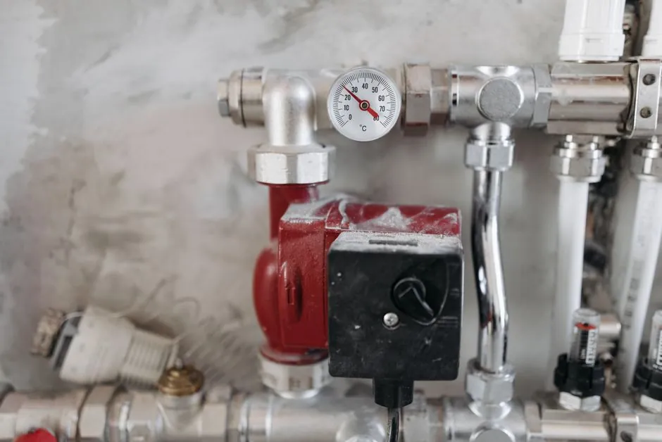
Flow direction is the single most often misread detail on a knife gate valve install: the cast body arrow may indicate normal flow, the seat side, or the closed-valve pressure direction, and on a unidirectional seat the three are not interchangeable [S1]. Installers who read the arrow alone routinely mount the valve backwards, lose shutoff at first pressure test, and have to cut the spool out.
This guide covers the field checks that matter before the spool hits the rack: body arrow vs SEAT marking vs P&ID flow arrow, unidirectional vs bidirectional seat behaviour, flange alignment, stem clearance, and the open-close test that catches most installation errors before hydrotest [S1][S2]. Knife gate valves are specified for thick stock, pulp slurry, biosolids, grit, and fibrous ragging where standard gate valve or ball valve designs plug or leak [S3][S5].
Reading the Body Arrow: Flow, Seat Side, or Pressure Direction?
The cast arrow on a knife gate valve body is ambiguous by design, and treating it as a plain pipeline flow marker is the most common installation error on unidirectional units [S1]. On many general-purpose industrial valves the body arrow matches normal process flow, but on knife gate valves the same arrow can also indicate the seat side or the pressure direction required to push the gate against the seat when the valve is closed.
Field rule: cross-check the body arrow against three independent sources before the valve is welded or bolted in. First, the SEAT marking cast on the body, which identifies the high-pressure side of the seat. Second, the P&ID flow arrow for the line, which shows normal process flow. Third, the closed-valve pressure direction, which on pump-discharge, dead-end, silo discharge and reverse-pressure service may be opposite to normal flow [S1]. If any two of these three disagree, stop and read the IOM and datasheet before lifting.
Unidirectional vs Bidirectional Seat: What Actually Changes at Install
Unidirectional knife gate valves rely on differential pressure to push the gate against the seat for shutoff, so the install direction is fixed by seat geometry and not by operator preference [S1][S5]. Mounting a unidirectional seat backwards removes the sealing force, and the valve will pass at any meaningful working pressure, with leakage rates that fail a bubble-tight acceptance test on the first hydrostatic cycle.
Bidirectional knife gate valves, including designs with patented seats such as the ITT Fabri C67S for pulp and paper service, are built to shut off from either flow direction and tolerate installation in either orientation relative to normal flow [S3]. For a knife gate valve on bidirectional duty, the body arrow still matters for actuator position and drain orientation, but it no longer dictates shutoff integrity. Even so, a bidirectional rating does not waive the IOM, datasheet, and drawing check; it only removes the seat-side constraint.
Pre-Installation Inspection: Body, Seat Area, Packing, and Flange Faces
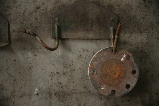
Pre-lift inspection should cover the body, stem, gate, seat area, packing, and flange faces, with any transit damage photographed and recorded against the packing list before the valve is set on the pipe [S2]. Welding slag, rust, and loose debris in the line are the next most common cause of seat scoring on first stroke, so the pipeline must be cleaned and blown through before the valve is bolted up.
Flange faces should be checked for flatness, gasket seating area condition, and any radial scores from previous gaskets. Gasket selection must match the pressure class, media, and temperature, and bolting must follow the IOM torque sequence, typically a star pattern in at least three passes, rather than a sequential round-by-round tightening that warps the face [S2]. For knife gate valves on slurry or fibrous service, also verify that the packing gland is accessible for future adjustment, since gland re-tension is the routine maintenance task that keeps the stem area from becoming a leak path.
Orientation, Stem Clearance, and Pipe Support
Stem-up vertical orientation is the default for most industrial knife gate valve installations, because it keeps the actuator, handwheel, or cylinder out of the process drain path and gives the maintenance crew straight access to the packing gland [S2]. Horizontal pipeline runs typically keep the stem vertical as well; horizontal-stem or stem-down mounting is used only where the actuator must clear an obstruction, and the rationale must be on the drawing, not a field decision.
Stem travel and actuator clearance must be verified before the valve is set, because the gate retracts fully out of the flow path when open and the bonnet or actuator needs unobstructed vertical space above the body [S2]. Pipe support on either side of the valve is non-negotiable: a knife gate valve is not designed to carry the pipeline weight, and an unsupported span will transfer bending loads into the body, warp the seat, and cause the very leakage the seat geometry was supposed to prevent. End connections, whether flanged, wafer, lug, or mechanical joint, must be aligned without forcing the pipe; forced alignment pre-loads the seat and is a documented root cause of high operating torque and seat damage on first stroke [S2].
Flange Alignment, Gasket, and Bolting Procedure
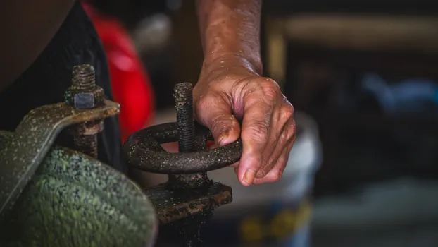
Flange alignment is checked with the bolts loose: the gap between the flange faces should be parallel within the gasket manufacturer’s tolerance, typically less than 0.5 mm across the diameter for soft gaskets and tighter for spiral-wound, before any bolt is torqued [S2]. Misaligned flanges concentrate bolt load on one side of the face, crush the gasket unevenly, and on knife gate valves the resulting face distortion can push the gate out of square with the seat.
Bolting follows the IOM pattern, which is usually a star or four-cross sequence in three or four passes, starting at roughly 30 percent of final torque, moving to 60 percent, and finishing at 100 percent on the last pass [S2]. Gasket compression should be even across the full face; recheck torque after the first hydrostatic test, since gasket relaxation and thermal cycling on first hot run can drop bolt load by 10 to 20 percent on soft gaskets. For valves supplied without a gasket, the linear guide of components must include a gasket rated for the design pressure, temperature, and media chemistry, not a generic fibre sheet substituted at site.
Open-Close Test, Hydrostatic Check, and Commissioning Records
Before the line is pressurised, the valve should be stroked fully open and fully closed at least once against a depressurised line, with the position indicator and travel stops confirmed against the IOM stroke length [S2]. On knife gate valves, an initial open-close cycle also seats the packing, lets the installer feel the actual operating torque, and surfaces any binding caused by a warped flange or a gate that was nudged out of square during bolting.
The hydrostatic test is then run at the pressure class specified on the body, with the valve in the half-open position so the test medium contacts both sides of the seat and the full body cavity [S2]. Any seat leakage above the acceptance criterion, usually zero visible leakage for resilient-seated knife gate valves on bubble-tight duty, is a reject and means the seat is contaminated, damaged, or installed on the wrong side. The same check applies to metal-seated units, where the leakage rate is governed by the project spec, typically expressed in millilitres per minute per inch of seat diameter. Records should capture installation orientation, torque values, stroke test results, and the as-installed flow direction relative to the body arrow, because that data drives the next maintenance decision when the seat or packing eventually needs replacement [S2].
When Knife Gate Valves Are the Wrong Choice

Knife gate valves are isolation-duty linear motion valves designed for thick, fibrous, abrasive, or solid-laden media, and they are not general-purpose drop-in replacements for other valve types [S5]. On clean gas, clean water, or high-pressure steam above the valve’s pressure-temperature rating, the sharp-edged gate and the soft seat materials that give the knife gate its shearing advantage become wear and leakage liabilities. For modulating service, the gate geometry and seat contact pattern are wrong; the knife edge erodes quickly under throttling duty, and a balancing valve or a control valve is the correct specification.
Selection discipline matters at install: a knife gate valve specified for high-consistency stock, lime mud, biosolids, or pulp slurry earns its place by cutting through fibres and wiping the seat clean, with full-bore flow when open and zero internal pockets where solids can pack [S3][S5]. The same valve on a clean chemical line, a high-temperature steam header, or a modulating control loop is a maintenance problem waiting to happen. The right rule, repeated across the pulp, paper, wastewater, and mining application notes, is to match the valve mechanism to the media, confirm the seat side and flow direction on the drawing, and document the install orientation before hydrotest [S1][S3][S5].
For plant engineers, the next trackable signal is the post-commissioning seat leakage rate on first hot run, logged against the body arrow direction and the seat-side marking from the IOM, since that single data point confirms whether the install direction is correct and predicts the first packing and seat service interval. Buyers evaluating total cost of ownership across isolation valves should also weigh the related balancing valve TCO math, since seat, packing, and actuation choices interact across the isolation valve fleet.