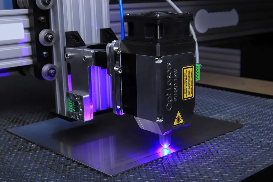
Laser triangulation, coded structured light, and passive stereo are the three dominant active 3D imaging modalities on production lines, and each maps to a different combination of standoff, accuracy, and motion tolerance [S1][S2].
The selection pivot is rarely the brand; it is whether the part is moving, whether the surface is textureless, and how many millimetres of field-of-view the application actually needs [S1][S4].
How the three methods actually build a 3D point
Laser triangulation projects a line (or point) at a fixed angle and uses one camera offset at a known baseline to read the displacement of that line on the sensor; each line becomes one cross-section, and stacked lines become a 2.5D height map or point cloud [S1][S5]. The pixel displacement along the camera axis is the direct measurement quantity, and a typical industrial setup targets a 40-50 mm field of view held to plus or minus 0.02-0.03 mm [S1].
Stereo vision uses two cameras separated by a known baseline and recovers depth purely from the disparity between the two views; no projector is required, so it works outdoors and at long range but depends on finding corresponding features in both images [S2][S5]. Structured light replaces one stereo camera with a pattern projector; the projector emits a sequence of coded patterns, the camera captures each one, and the algorithm triangulates per-pixel depth from the pattern deformation, so it works on textureless parts where pure stereo would fail [S5][S2].
Comparison matrix across the four decision criteria
On accuracy at short standoff (under about 200 mm), laser triangulation is the strongest of the three, routinely hitting plus or minus 0.02 mm on a small field of view, while structured light typically lands in the plus or minus 0.05-0.2 mm band depending on projector resolution and baseline [S1][S5]. Stereo vision in the same range sits lower still because its depth error scales with the square of the standoff and inversely with baseline length, so it needs either a wide baseline or a long standoff to be useful [S2][S4].
On motion tolerance, stereo is the most forgiving because it captures a full frame in a single exposure, structured light can be frozen with a pulsed projector for short windows, and laser triangulation strictly requires either part or sensor motion to build up a profile [S1][S2]. On surface-dependence, structured light and laser triangulation are largely texture-independent because they supply their own illumination pattern or line, while passive stereo degrades sharply on specular, transparent, or featureless surfaces [S5][S3]. On cost and integration, stereo is the cheapest to rig (two off-the-shelf cameras plus a calibration target), coded structured light needs a calibrated projector-camera unit, and laser triangulation usually ships as a factory-calibrated smart sensor [S5].
Where each method is the right answer
Choose laser triangulation when the part is already moving on a conveyor or robotic end-effector and the spec is sub-100 micrometre height accuracy on a 30-80 mm field of view; a typical 2D measurement like seam step or glue-bead volume is exactly the use case it was built for, because height is the directly measured quantity rather than something inferred from shading [S1][S4]. The trade-off is that any change in standoff, surface reflectivity, or part speed must be re-characterised, and the laser line is the single point of failure if it is occluded.
Choose coded structured light for full-field snapshots of stationary or slowly moving objects, especially textureless plastic, metal blanks, and bin-picking parts, because the projected coding pattern supplies the correspondence that stereo would otherwise need to find in the image [S2][S5]. Choose passive stereo for outdoor scenes, large work envelopes, or any application where eye-safety classification, projector lifetime, or multi-sensor crosstalk rules out an active illuminator [S2][S6].
Selection rules that survive contact with a real line
First rule: pin down the field of view and the tolerance before the sensor brand, because FOV and tolerance together decide whether a single triangulation head is enough or whether a multi-head rig is mandatory [S1]. Second rule: confirm the motion budget; if the part is stationary and the budget for an indexing stage is zero, structured light is the default, and triangulation is a forced mismatch [S1][S2]. Third rule: check the surface; mirrored, transparent, or highly specular finishes break laser triangulation through saturation and break passive stereo through missing features, leaving coded structured light as the surviving option or pushing the system toward photometric or deflectometric methods [S5][S3].
For bin-picking and palletising cells the pattern is typically structured light at the picking station and laser triangulation at the post-pick inspection station, because they optimise for different jobs rather than competing head-to-head [S2][S5]. For reference designs, a structured light scanner project sequence is the right starting point when a stationary full-field depth map is needed, while a 3D scanner covers the triangulation sensor family on moving lines. Lighting for either method is non-trivial, and pairing the projector with a vetted vision light source is what actually determines whether the coded pattern survives the ambient factory floor.
Limits, failure modes, and what the spec sheet does not tell you
Laser triangulation fails in three named ways: occlusion of the line by the part geometry, specular saturation on shiny metal, and standoff drift when the part walks vertically out of the calibrated range; each one shows up as missing data at the edge of the height map rather than as a wrong number, which is a useful diagnostic [S1][S4]. Structured light fails when the pattern coding is washed out by strong ambient light, when the projector overheats in high-duty-cycle cells, or when multiple units interfere, which is why high-end vendors gate the projector with a hardware trigger and a unique code per unit [S2][S5].
Stereo vision fails on textureless surfaces because the correspondence step has no features to match, and its accuracy collapses at short standoff because depth error scales with standoff squared divided by baseline; a practical floor is roughly 0.1% of the working distance for a well-calibrated rig, which is the main reason stereo is rare in micrometre inspection [S2][S4]. Across all three, integration with the rest of the machine vision imaging stack, frame grabber, vision controller, and identification downstream, is the hidden cost, and HALCON-style 3D operators (more than 1,800 in the MVTec library alone) are what turn a raw point cloud into a pass/fail signal [S5].
Sourcing, standards, and what to verify before purchase
There is no IEC or ISO standard that mandates one 3D method over another for industrial inspection; selection is governed by application fit and by the underlying eye-safety classification of the projector, which for laser-based units falls under IEC 60825-1 and, in many European plants, the parallel ATEX / machinery directives for the cell as a whole.
Trackable signals to watch over the next quarter: factory-floor reference designs that pair a structured-light station with a downstream triangulation station for in-line metrology, and the slow migration of FMCW coherent methods out of the automotive LiDAR domain and into short-range industrial cells, where they promise immunity to ambient light and multi-sensor crosstalk at the cost of a much higher bill of materials [S2].
This topic is covered further in Lithium Refinery Process Control and Online Analyzers: Specs, Methods, Stage Map.