
A mechanical limit switch converts physical movement into a circuit change with high-current capability, but wear, contact bounce, and direct target contact define its main limitations [S1][S3].
Used on conveyors, machine tools, elevators, cranes, gates, packaging equipment, and robotic systems, limit switches remain practical where a moving part must establish a definite end or interlock position [S2][S3].
Operating principle and practical scope
A limit switch is an electromechanical device with an actuator mechanically linked to electrical contacts. Physical movement of the actuator changes a normally open contact to closed or a normally closed contact to open, allowing the switch to detect objects and control machines [S1].
The operating position is where the contact changes from its normal NO or NC state, while the release position is where it returns [S3][S5].
Common mechanical formats include lever, push, rotary, and whisker types. Mechanical limit switches are available in lever, push, rotary, and whisker types, with a rotary switch operated by rotation [S3]. A practical limit switch therefore fits a machine that deliberately moves into a mechanical stop or actuating surface.
Advantages that justify installation
Limit switches combine three commercially important benefits: they can switch comparatively large currents, cost less than many electronic sensing systems, and remain intuitive to operate and maintain [S3][S4]. Limit switches have the ability to handle large currents [S4].
The mechanical architecture is straightforward rather than specialized. Plug-in modular construction can simplify installation because the receptacle is fixed to the fixture and the switch module can be mounted into it [S7]. The plug-in modular design simplifies installation by using a mounted receptacle and a removable switch unit [S7].
Detection does not depend on the visual properties of the target. The trade-off is that the target must physically reach and operate the actuator [S3].
Failure modes and operating constraints
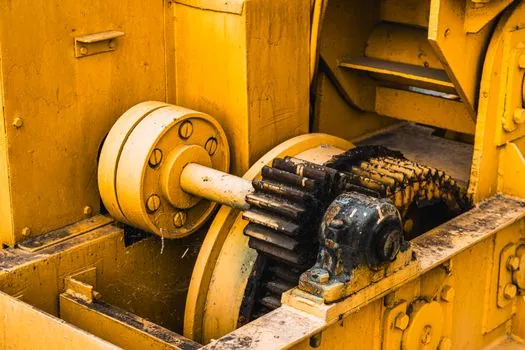
Wear is the central lifecycle limitation because repeated actuator movement and contact operation create mechanical wear, and failed limit switches are generally mechanical in nature [S3][S5]. Actuator movement creates wear, and limit-switch failures are generally mechanical in nature [S3][S5].
Contact bounce is another constraint. Rapid contact movement can produce repeated make-and-break transients rather than one clean state change [S3][S4].
Environmental qualification remains essential.
Contact sensors versus non-contact options
Limit switches support high-current switching and direct mechanical actuation [S1][S4]. Their disadvantages are physical contact, wear, bounce, and slower response, whereas proximity and photoelectric devices can detect without touching the target [S1][S3].
A proximity sensor is preferable when contact is unacceptable, rapid response matters, or the target cannot be allowed to strike the sensor. A photoelectric sensor can suit non-contact detection where target reflectivity, color, opacity, or beam alignment can be controlled. For rotary shafts where absolute position is required, an absolute encoder provides a different class of measurement rather than an end-position contact signal.
Actuator and contact selection by application

Contact action must match the control task. Momentary action is appropriate for a passing target and a momentary command. Maintained action is appropriate when the equipment must remain commanded after the target has passed [S3][S5]. Overhead cranes use rotary limit switches for hoisting and lowering limits, while machine tools commonly use limit switches to constrain axis travel [S3][S5].
Costs beyond the purchase price
The low acquisition cost of a limit switch does not eliminate lifecycle expense. Mechanical parts wear, actuators may require adjustment, and plugs or receptacles add installation components [S3][S7]. A lifecycle assessment should include replacement frequency, machine downtime, actuator alignment effort, and the consequences of an incorrect limit signal.
Failures can be mechanical even when the original switch appears inexpensive. The Limit Switch TCO: Lifecycle Cost Decision Framework provides a practical structure for comparing purchase price against operating life, maintenance effort, and machine-risk exposure.
Application also determines the environmental and electrical package. Steel, mining, ports, lifting equipment, and construction machinery may require high-temperature, corrosion-resistant, or explosion-proof variants [S4]. The specification should therefore cover contact rating, actuator type, mounting, ingress protection, temperature range, cable entry, and the applicable hazardous-area certification for the installation.
Application fit and maintenance controls

Limit switches are strongest for elevators, automatic gates, conveyors, CNC machines, robots, packaging equipment, garage doors, hoists, and machine-axis interlocks where a target has a repeatable physical stopping or actuating point [S2][S3]. They are weak fits for non-contact stop detection, very high-cycle positioning, inaccessible mechanisms, or applications where contact impact would damage the target.
Maintenance should include checking actuator alignment, operating and release points, mounting security, linkage play, contact bounce behavior, and contamination around the operating head [S1][S3]. Maintenance frequency should follow observed cycle count rather than a generic calendar interval because impact loading and misalignment can dominate wear.
A procurement decision should test four criteria in order: required current and control function, target geometry and available travel, environmental severity, and expected cycle rate. If those four pass, the limit switch usually offers a simpler and less expensive solution than an electronic position sensor. If any one fails, a proximity, photoelectric, or encoder-based solution is more defensible.
The next engineering check is to record the target stroke, actuator operating force, switch repeatability, electrical load, cycle rate, and hazardous-area classification. Comparing those six values with the proposed switch model and maintenance plan will expose whether the cost advantage survives the full operating cycle.