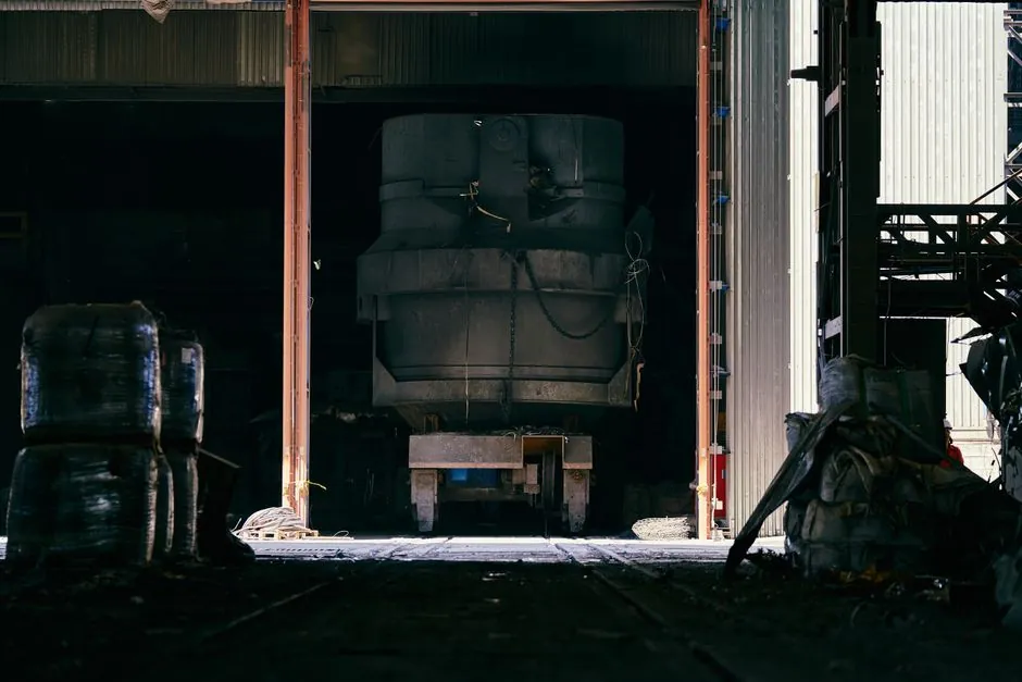
A linear module specified for a steel mill is not a clean-room component with a heavier paint job. Ambient temperatures near a continuous caster routinely run 40–60 °C, airborne iron-oxide scale and rolling-mill cooling water mist coat every surface, and duty cycles hit 24/7 rather than the 8 h/shift typical in electronics assembly [S3]. The selection that survives is the one that matches drive mechanics, housing material, and sealing to those realities before repeatability is even discussed.
For roughing and finishing stands, coil-handling transfer cars, and tundish car positioning, the practical envelope is a heavy-duty linear module with a steel or reinforced-aluminum profile, repeatability of ±0.05 mm or better on screw-driven axes, and a documented L10 bearing life at the actual working load, not the catalog maximum. Mills that ignore this distinction replace actuators on a 12- to 18-month cycle.
Selection Criteria: Load, Stroke, Duty Cycle, Environment
The four inputs that actually decide the build are payload mass, total stroke length, duty cycle (cycles/h), and the worst-case ambient condition [S1][S2]. For a coil transfer car, payload commonly lands in the 5,000–25,000 kg band and stroke runs 3–10 m, which immediately eliminates most belt-driven, aluminum-housed catalog modules sized for pick-and-place.
Duty cycle drives the thermal budget. A mill running 24/7 at 30 cycles/h imposes roughly 720 cycles per day, or about 260,000 cycles per year per axis, before any derating for starts/stops under load [S5]. For continuous caster cutoff or roller-table indexing, that figure is the baseline, not the peak.
Environment sets the sealing and material class. Iron-oxide scale, lubricant aerosols, and water mist from cooling headers demand at minimum IP54 protection on the carriage and drive, with bellows or metal way covers on the stroke; stainless or nickel-plated hardware on exposed fasteners; and a way-lubrication system that tolerates contamination rather than depending on a clean factory-air supply [S1][S3].
Drive Type Comparison: Ball Screw, Belt, Rack and Pinion, Linear Motor
For mill-floor axes, drive selection is largely a function of stroke, load, and required repeatability. Ball-screw drives deliver the highest endpoint accuracy and are the default for short-stroke, high-precision mill auxiliaries such as side-guide adjustment and roll-bender positioning, where repeatability of ±0.01–0.05 mm is achievable. Belt drives are limited to roughly 500 µm endpoint accuracy and are best kept away from vertical or high-load mill duties; their use case is long horizontal transfer where cost per meter of stroke matters more than precision [S5].
Rack-and-pinion drives are the workhorse for long horizontal travel under heavy load: walking-beam transfer, coil cars, and roller-table indexers with strokes above 2 m. They tolerate contamination better than ball screws and can move multi-tonne payloads when paired with a helical rack and a servo gearbox sized for 1.5–2x the peak torque. Linear motors excel where stroke is short-to-medium and the environment can be kept clean (e.g., inside enclosed roller-table housings), but they need a linear encoder for closed-loop position and scale protection; in an open mill bay, the encoder and the forcer's magnet track both become maintenance liabilities.
On a like-for-like basis, the engineering trade-off reads: ball screw = highest accuracy, shortest practical stroke, highest contamination sensitivity; belt = lowest cost per meter, only for horizontal light load; rack and pinion = best fit for heavy horizontal mill transfer; linear motor = highest dynamic performance, cleanest environment only.
Housing and Guide Materials: Steel vs Aluminum in Mill Service
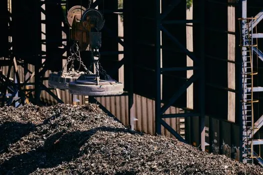
Aluminum extrusions dominate catalog linear modules because they extrude cost-effectively into a wide range of profiles and keep moving mass low [S3]. In a mill, that mass advantage disappears the moment the housing is caked with scale and oil, and aluminum's lower stiffness shows up as deflection under multi-tonne payloads. Steel or steel-lined housings are stiffer and more dimensionally stable under thermal cycling, at higher unit cost and weight [S5].
For the guide element itself, a recirculating ball linear guide sized with a minimum static-load safety factor of 1.5 (dynamic L10 safety factor of 2.0 or better for 24/7 service) is the standard choice. Crossed-roller guides give higher rigidity and accuracy in a smaller envelope but are more sensitive to contamination and side-impact loads, so they belong in enclosed or protected mill auxiliaries, not on an open transfer car. The general rule from integrators: specify the housing and guide for the worst steady-state load plus a defined shock factor, then verify the bearing L10 life at the real duty cycle, not the catalog maximum [S1][S5].
Sizing Pitfalls Specific to Mill Duty
The most common and expensive error is sizing to catalog maximums. Selecting a module whose rated load equals the actual running load guarantees under-spec'ing, because peak loads during coil handling, scale buildup, and cold-start torque transients routinely hit 1.5–2x the steady-state figure [S5]. Undersizing can also void the manufacturer's warranty on the drive and bearings, a point that procurement often misses until the first failure.
Oversizing is the opposite mistake: paying for capacity the line never uses. The pragmatic balance is to size for the verified peak load with a 1.5–2.0x safety factor on drive torque, then confirm L10 bearing life at the actual cycle count, and check critical-speed and buckling limits on any screw-driven axis above 1 m of stroke [S1][S2].
Mounting is the second pitfall. Mill mezzanines and roller-table pits rarely give a clean base-mount surface. Linear modules that only offer base mounting force the integrator to fabricate brackets, which adds cost, alignment time, and a documented source of repeatability loss. Modules with T-slot extrusion, positive-locking centering rings, and multiple mounting faces (base, side, top) cut integration time and keep alignment repeatable across rebuilds [S5].
Typical Mill Applications and the Specs That Fit
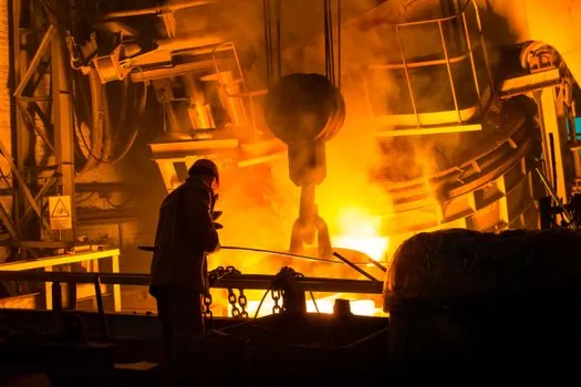
For side-guide adjustment on a rolling stand, repeatability of ±0.02 mm and a ball-screw drive with a steel housing, IP54 sealing, and stroke of 200–500 mm is a typical build. Roll-bender positioning calls for similar precision with longer stroke (500–1500 mm) and higher thrust, often served by a heavy-duty ball-screw module in a steel profile [S1][S3].
Coil transfer cars and walking-beam conveyors are the domain of rack-and-pinion modules with strokes of 3–10 m, payload ratings in the 5,000–25,000 kg band, and absolute or incremental linear encoder feedback. Repeatability here is usually specified at ±1–2 mm, which is well within rack-and-pinion capability and does not justify the cost of a ball-screw solution. Tundish car and ladle turret drives fall in the same category, with the additional requirement of redundant braking and absolute-position retention through power loss.
Who This Is For, and Where the Catalog Module Fails
This spec profile is built for rolling-mill stand auxiliaries, coil and slab handling, continuous-caster sections, and hot-strip mill run-out tables, i.e., heavy industry with high duty, contamination, and thermal cycling. It is not for clean-room semiconductor or medical lab automation, where aluminum-housed belt or linear-motor modules with sub-micron accuracy are the correct choice, not an over-engineered steel mill module [S3].
For engineers cross-referencing a mill-floor linear actuator build against broader linear motion system design, the rule of thumb is to start from the worst environment, then back-derive the drive. A module that can survive the mill bay will run cleanly in any packaging or material-handling line; the reverse is not true.
Verification, Standards, and Sourcing

Before signing a purchase order, confirm three things in writing: a sizing calculation showing L10 bearing life at the actual cycle count and peak load; a duty-cycle and temperature derating curve for the motor and drive; and a sealing rating validated against IP54 or higher on both the carriage and the drive enclosure [S1][S5]. For European mill builds, ATEX classification may apply in areas near hydraulic or lubrication reservoirs, but should be specified only when the zoning study has identified a real hazard, not as a default.
Supplier evaluation should weigh lead time on spare carriages and drive belts, local service coverage, and the availability of a sizing tool that accepts real cycle data rather than a single load point. Mills that standardize on two or three qualified module families and document the sizing rationale per line typically see 3–5x longer mean-time-between-overhaul on linear axes than sites that re-spec every project. The next trackable signal is the release of mill-rated rack-and-pinion modules with integrated absolute encoders and IP65 sealing, which several suppliers added to their catalogs in the 2025–2026 window and which are worth short-listing for any greenfield caster or hot-strip mill revamp.
See also our earlier report, Access Control System Selection for Oil and Gas Facilities: Spec Map 2026.