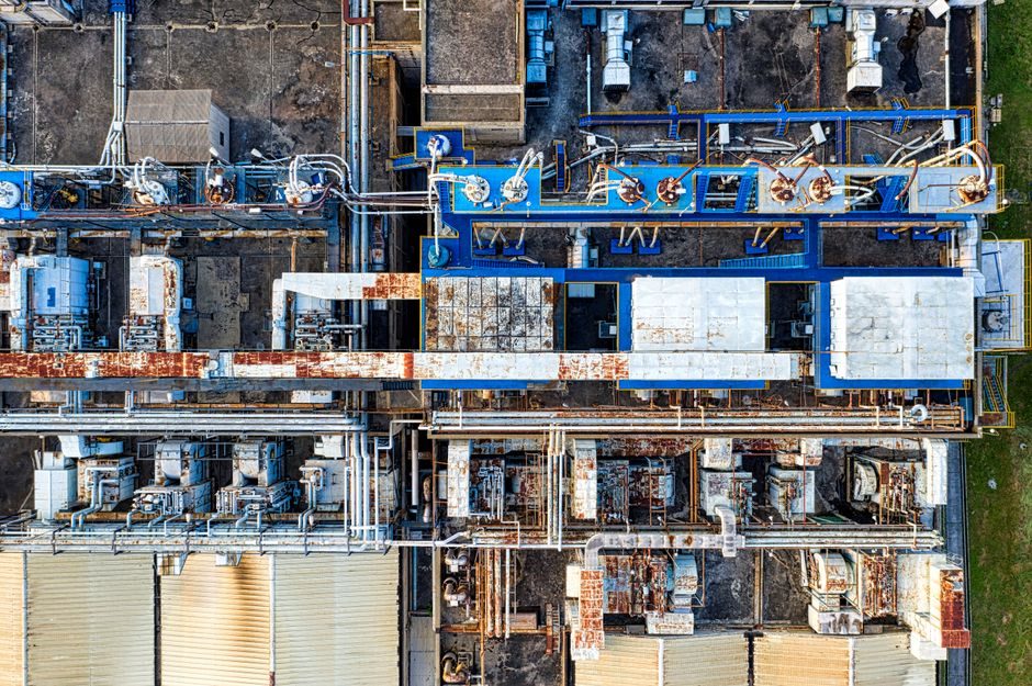
Lithium-ion cell production is a multi-stage capital equipment chain — electrode mixing, coating, drying, calendaring, slitting, notching, stacking/winding, electrolyte dosing, sealing, formation, aging and grading — where each station has its own tolerance class, cleanliness class and throughput benchmark [S1].
The mainstream cell formats the line has to serve are cylindrical (e.g. 18650, 21700), prismatic (hard-case aluminium) and pouch; each format drives different stacking/winding kinematics, different laser-welding optics and different formation-current channel counts [S1][S4].
Front-End Electrode Process: Mixing Through Calendaring
The front end is where most of the line capex concentrates: planetary or double-helix mixers homogenise cathode slurry (NMC/LFP with PVDF binder in NMP) and anode slurry (graphite/SiOx with CMC/SBR in water), and the next inline stations are slot-die or comma-bar coaters drying in 80–150 m length floatation or floating-belt ovens [S1].
Calendaring follows drying: roll-pressure control on the order of 20–80 t per metre of web width and inter-roll temperature control in the 80–120 °C band set the electrode compaction density that downstream cell energy-density targets depend on [S1]. Slitting and notching then cut the dry electrode to width with a typical ±0.2–0.5 mm tolerance and burr class controlled to keep die-cutting tool life predictable [S1].
For a buyer comparing front-end tools, the decision criteria that actually move total cost of ownership are line speed (m/min), web-width support (≤650 mm pilot, 1000–1300 mm mass production), and electrode-dust control — most rejects trace back to mixing-coating-drying interface contamination rather than the coater itself [S1].
Cell Assembly: Stacking vs Winding and Laser Welding
Stacking lines (Z-folding or stacked-pouch) dominate pouch and large-format prismatic EV cells because they accept thicker cathodes and high-silicon anodes; winding lines remain the default for cylindrical 18650/21700 cells because of the inherent cycle-rate advantage at that geometry [S1]. Stacking throughput on current Chinese ODM lines sits in the 6–12 ppm (parts per minute) band per stacker head, with multi-head configurations scaling this linearly [S4].
Laser welding — fibre-laser tab-to-tab and cap-to-can — is the dominant joining process, and Wuhan-based automation suppliers have built dedicated soft-pack and prismatic welding cells around it, integrating vision-based seam tracking and pulse-mode current feedback for spatter control [S4]. For tab welding on aluminium pouch cells, the practical weld-width window is 1.2–1.8 mm at a focal spot of ~50 µm, with overlap kept under 5% to avoid through-penetration [S4].
The stacking vs winding decision is not symmetric: stacked cells give better internal-resistance uniformity in large-format prismatic cells, but the equipment footprint and per-station cost run 1.4–1.8× the winding line, so for cylindrical 21700/4680 lines the answer is almost always winding [S1][S4].
Formation, Aging and Grading: Where Yield Is Won or Lost
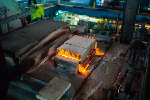
Formation — the first controlled charge/discharge that builds the SEI (solid-electrolyte interphase) — runs at 0.1–0.5 C charge rates for 12–48 hours per cell, with temperature controlled at 25–45 °C, and is the single largest electrical-energy consumer in the cell-making process [S1]. Aging follows formation: cells are stored at controlled temperature (typically 25–45 °C) for 7–28 days so early-life defects surface as voltage or self-discharge drift.
Grading (capacity sorting by coulomb-count and internal-resistance binning at 1 kHz AC) closes the loop: cells out of the same production batch are paired into modules/packs so that pack-level capacity variance is kept under ~2% — anything looser shows up as cycle-life spread in the field [S1]. The formation channel cabinet is where the data feedback to the front end comes from: a single formation cabinet typically holds 256–1024 channels, with high-end lines pushing to 2048+ channels per cabinet to compress factory footprint [S1].
For OEM/ODM factory buyers, the grading accuracy spec — typically ±0.3% capacity and ±0.1 mΩ IR — matters more than the formation hardware's brand, because grading error directly becomes pack-level kWh loss [S1][S4].
Cleanroom, Dry-Room and Electrolyte Filling Constraints
Lithium cell assembly runs in dry-room conditions: dew-point control in the −40 °C to −60 °C range is standard for electrolyte filling and cell-stacking enclosures, with the strictest window sitting on the LiPF₆ salt handling and electrolyte dosing stations [S1].
Electrolyte injection volumes are tight: a 21700 cylindrical cell takes ~3.5–4.5 g of electrolyte, prismatic EV cells typically 80–250 g, and dosing tolerance is held to ±1–2% — under-fill kills cycle life, over-fill raises internal pressure and risks venting [S1]. Vacuum-pre-fill and pressure-driven post-fill soaking are the two dominant dosing strategies, with the post-fill soak step typically running 30–120 s before the cell is sealed.
Cleanliness class for the assembly room sits in the ISO 7–8 band for the cell-assembly area, tightening to ISO 6 around the laser-welding optical path to keep weld-pool spatter and electrode-dust off the focusing optics [S1][S4]. A practical rule of thumb: a single 50 µm metal particle inside a wound cell is a 100% scrap event, so particulate counts on the assembly floor are tracked as a first-class yield metric, not a housekeeping metric.
Standards, Transport and the Export-Compliance Linkage

The manufacturing line itself is governed less by a single IEC standard and more by customer-specific packs (the cell-maker is audited against the cell-buyer’s incoming-quality spec), but the transport and shipping rules downstream are sharp: lithium cells are UN Class 9 dangerous goods, with specific UN numbers — UN3090 (lithium metal), UN3480 (lithium-ion standalone), UN3091 and UN3481 for the variants where the cell is packed with or contained in equipment [S5].
That UN-number split is not a paperwork detail: it dictates packaging group, labelling and the testing dossier (UN 38.3 altitude, thermal, vibration, shock, short-circuit and impact tests) the cell must pass before air or sea freight is allowed [S5]. For a buyer comparing equipment, the practical consequence is that any formation/aging line has to be able to produce the per-cell voltage, IR and self-discharge data that the UN 38.3 pre-shipment test and the downstream IEC 62133 or UL 1973 safety report will reference.
Buyers should also align the production MES (manufacturing execution system) data schema to those reports from day one — retrofitting traceability after the line is commissioned is a 6–12 month engineering project that nobody budgets for, and it is the same data schema that flows into battery passport pilots in the EU and similar regulations elsewhere [S1].
Selection Criteria and 2026 Sourcing Signals
For a buyer comparing equipment vendors, four criteria dominate: line-yield on the buyer’s electrode chemistry, factory-acceptance-test (FAT) and site-acceptance-test (SAT) protocols, local service response (mean time to repair in hours), and MES/traceability interface maturity [S1][S4]. Most Chinese ODM equipment factories in the Hubei/Wuhan, Jiangsu and Guangdong clusters now ship FAT-tested lines with PVDF/NMP or water-based slurry recipes pre-validated against NMC811 and LFP cathodes, which compresses ramp time from 12+ months to roughly 6–9 months for a greenfield gigafactory [S4].
For process-control choices on the formation/aging line, the CPU and PLC instrumentation spec bands published in 2026 are the reference ceiling, since formation channel counts are now pushing I/O densities that only mid-range PLCs or industrial PCs can serve. Adjacent laser-welding procurement should be cross-checked against the arc-welding 2026 spec bands because the same fibre-laser and seam-tracking stack is increasingly shared between battery-tab welding and heavy-equipment welding lines.
For component-level specifications, see additive manufacturing material, anti static equipment, and linear guide.