
Load cell selection collapses to four hard numbers: required capacity in kg or N, accuracy class (OIML R60 / NTEP HB44), physical envelope (height, bolt-circle, cable entry), and output interface (mV/V, 4-20 mA, RS-485, IO-Link). Once those four are pinned, the form factor and manufacturer list narrow by an order of magnitude [S1][S2].
Across packaging, tank, vehicle, and onboard agricultural duty, the dominant error source is not sensor noise but mechanical side-load and moment loading on a cell that was never designed to reject them, so the application review must come before the catalog review [S1].
Step 1: Working Load Calculation and Capacity Oversize
The minimum rated capacity follows a fixed arithmetic: Minimum capacity = (Net weight + Tare weight) x Dynamic factor x Safety factor, with dynamic impact typically adding 20-50% on a hopper or platform and a 1.5x safety factor applied on top [S2]. A worked example: a 1000 kg tank plus 200 kg hopper at 1.3 impact and 1.5 safety equals 2,340 kg, which forces a 2,500 kg or 3,000 kg cell, not a 2,000 kg cell [S2].
For fatigue or cyclic loading (force testing, dynamometers, crane load monitoring), FUTEK recommends operating at 50% or lower of rated capacity, or specifying a fatigue-rated cell, because the rated cycle life of a standard cell assumes a much lower utilisation profile [S1]. Undersizing in this regime is the single fastest path to strain-gauge fatigue and zero-shift drift.
Step 2: Form Factor by Capacity Band
Capacity alone does not pick the cell, but the capacity bands published across the major guides map cleanly to the canonical mechanical geometries. Single point and bending-beam cells cover 0.1-50 kg duty for packaging machines and balances; shear beam and S-type cells cover 50-5,000 kg for pallet, hopper, and tank scales; canister and ring-torsion cells cover 5,000 kg to 100+ tonnes for truck scales and weighbridges [S2]. Single point cells are typically specified under 1,000 lb (about 450 kg), single ended beam between 500 lb and 20,000 lb (about 225 kg to 9,000 kg), and S-beam under 10,000 lb (about 4,500 kg) per cell [S4].
Form-factor trade-off: single point cells give the best off-centre error correction for a platform but cap out in capacity; S-beam cells handle both tension and compression but reject side load poorly; double-ended shear beams are the workhorse for onboard vehicle weighing up to 150,000 lb because their bolted-end design neutralises side force [S4][S5]. A load cell module assembly adds the mounting hardware, stay-rod, and lift-off protection that a bare cell cannot supply on its own, and is what most tank and silo installations actually buy.
Step 3: Mounting, Side Load, and Cable Entry
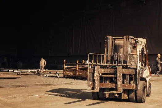
Mounting style is a hard constraint: female/male thread, in-line, side mount, flange mount, through-hole, or compression washer each dictate the cell's geometry, and extraneous side load and moment increase combined stress, accelerating fatigue and degrading accuracy if the wrong style is forced into service [S1]. For tank and hopper installations the load cell module approach (compression canister plus self-aligning hardware plus integrated lift-off protection) is the safer default over a bare S-beam, because the module absorbs thermal expansion and pipe-work forces that would otherwise side-load the sensor.
Cable entry direction (side vs bottom) affects IP rating and water-purge behaviour; bottom-entry with a vertical gland is preferred for IP68/IP69K food and washdown duty, while side-entry suits retrofit truck-scale installations where the conduit run is horizontal [S1][S2]. The matched indicator or amplifier should be specified together with the cell so the mV/V sensitivity, bridge resistance (commonly 350 ohm or 700 ohm), and excitation voltage are compatible end-to-end [S1].
Step 4: Environmental Derating and Regional Certification
Environmental derating is geographic. Nordic installations at -40 deg C add 15% capacity margin for ice loading and prefer 17-4 PH stainless steel for road-salt corrosion resistance; Southeast Asian sites at 90% relative humidity and monsoon exposure require IP68/IP69K stainless with moisture weight in the tare (typically 2-5%); Middle Eastern sites above 50 deg C lose roughly 10% capacity at 100 deg C and need sand-resistant cable glands and high-temperature alloy [S2].
Legal-for-trade certification differs by market: NTEP HB44 in the US, OIML R60 in Europe, and CCC in China, and the accuracy class plus the number of verification intervals (n) on the certificate must match the duty [S2][S3]. Non-legal applications (process control, force testing, in-line checkweighing) can skip trade certification but should still target a documented combined error budget of 0.03% to 0.25% of full scale, which is the typical range for industrial-grade strain-gauge cells.
Step 5: Output Signal and System Integration
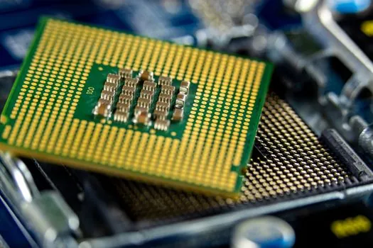
Output is the cell-to-controller interface and is fixed at purchase. Native strain-gauge output is mV/V, typically 2 mV/V at rated load with 10 VDC excitation, which requires a close-coupled amplifier to convert to 4-20 mA, 0-10 V, RS-485/Modbus, IO-Link, or a wireless link for the PLC or indicator [S1][S3]. HART, PROFIBUS PA, and FOUNDATION Fieldbus are process-instrument buses and are not native load cell outputs; you reach them only by pairing the cell with a digital transmitter that supports that protocol.
For multi-cell systems (tanks on three or four legs, truck scales with 6-12 cells), specify a summing junction box with individual cell trimming, or a digital load cell module that handles trim and diagnostics on-board; without it, off-centre loading and cell-to-cell sensitivity mismatch produce reading errors of 1-3% before any calibration adjustment [S3]. Order system calibration as one line item with the cell and indicator so the millivolt-per-volt sensitivity, shunt-cal resistor, and traceable test weights are matched at the factory [S1].
Step 6: When the Mainstream Choice Is Wrong
A single-point cell is the wrong pick for any platform over about 1 m x 1 m or over 1,000 lb, because the off-centre error correction that makes single-point cells attractive on small bench scales collapses outside that envelope [S4]. An S-beam is the wrong pick for tank or hopper duty with a swinging discharge auger, because the side loads from the auger motor will side-load an S-beam faster than its strain-gauge fatigue limit, even at well-under-rated capacity [S1][S4]. A standard stainless cell is the wrong pick for any duty above about 80 deg C continuous or in cryogenic service below about -40 deg C, where matched-temperature alloy or a hermetically sealed cryogenic cell is required [S1][S2].
For OEM high-volume builds (medical scales, checkweighers, retail bench scales), single point cells in 5 kg to 100 kg capacities remain the most cost-effective option, and the load cell category page covers the parametric filter typically exposed on supplier sites. For heavy-capacity truck and rail scales, double-ended shear beams and canister cells dominate, while a complementary article on How to Choose a Load Cell walks through the same workflow with a stronger focus on indicator and junction-box pairing.
Shortlist Logic and Sourcing Check
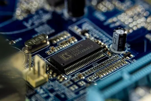
The shortlist is the intersection of capacity band, mounting geometry, output protocol, IP rating, and regional certificate. Confirm that the cell's combined error spec (nonlinearity + hysteresis + creep, typically 0.03-0.25% FS for industrial grade) is two to three times tighter than the system's required weighing error, and that the cell's deflection at rated load is compatible with the mechanical structure (a 2,000 kg canister cell can deflect 0.1-0.4 mm at full scale, which matters in low-headroom installations) [S2][S3].
Trackable signals to monitor: OIML R60 revision activity (R60 is the European accuracy-class standard covering verification intervals and minimum dead-load output return), NTEP HB44 certificate-database updates for cells already on the US market, and any IECEx or ATEX Ex nA / Ex tb certification for cells going into Zone 2 or Zone 21 dust environments [S3]. For projects that combine weighing with position or motion feedback on the same structure, the linear guide and crossed roller guide categories address the kinematic side, and the construction machinery and equipment index covers the platform-scale and weighbridge side where the highest-capacity cells are deployed.