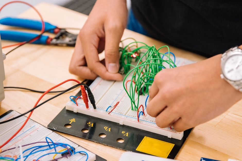
Loop impedance testers like the Megger LT320-FR publish a 2-wire/3-wire 500 V range with ±2% accuracy and CAT III 300 V rating [S2], and a fault-loop tester like the Sonel MZC-306 has gained product approval from Network Rail for rail-side commissioning work in 2025 [S5]. Those numbers fix the tester category: a hand-held, periodic, single-phase AC safety verifier, not a continuously installed transducer.
Power meters (and their multi-function variants) sit on the same conductors but answer a different question — how much energy passed, at what power factor, with what harmonic distortion, over a billing or load-shedding interval. Mixing the two is the most common audit finding on retrofit jobs: a tester is used once at handover, a power meter stays for years, and a project spec that asks for "loop testing capability" inside a revenue meter misleads the buyer.
What each instrument actually measures
A loop impedance tester injects a known test current between line, neutral, and earth, then derives Zs (earth-fault loop impedance) and the prospective short-circuit current Ipf. Published units typically resolve 0.01 Ω on the low range and read up to several hundred ohms on the high range, with the LT320-FR specified at 500 V and ±2% basic accuracy on a 2-wire/3-wire measurement [S2]. A loop tester used in this role is the only practical way to prove that an overcurrent device will trip within the disconnection time required by the installation standard.
A power meter instead samples voltage and current on a live feeder, integrates to kWh/kVArh, and typically logs up to the 63rd harmonic on the THD channel. Class 0.2S / Class 0.5S accuracy is the common revenue-grade split; IEC 62053-22 governs the 0.2S/0.5S active-energy classes, and IEC 62053-23 covers reactive energy — these are the documents to demand in the meter datasheet, not the tester datasheet. A multifunction power meter adds per-phase voltage, current, power factor, frequency, demand, and event logs, but still does not perform a one-shot Zs measurement.
Decision criteria: 2-wire vs 3-wire, CAT rating, accuracy, and wiring
On the tester side, four specs settle the comparison fast: number of wires tested, test voltage, basic accuracy, and installation overvoltage category. The Megger LT320-FR is published at 2-wire/3-wire, 500 V test, ±2%, and CAT III 300 V [S2]; competing products in the same Megger LT300 family cover a comparable envelope. Buyers on three-phase industrial boards should also check the 400 V / 690 V range and confirm the instrument carries a CAT IV rating if the test point is upstream of the main switchboard — a CAT III instrument can be over-ranged by an external lightning or switching surge on a long LV feeder.
On the meter side, the equivalent comparison is the accuracy class, the communications stack, and the CT/PT ratio programming window. A 0.2S meter is the floor for utility revenue transfer, a 0.5S meter covers sub-billing, and a 1.0-class meter is the typical process-load budget option. Wired protocols split between Modbus RTU on RS-485 (common, simple, multi-drop) and DLMS/COSEM or M-Bus for AMR; Ethernet-APL and IEC 61850 appear in MV and process-plant retrofit work. Decision rule: a Class 0.2S meter with Modbus RTU and a measured THD channel covers 80% of industrial energy-management tenders; only specify IEC 61850 if the site already runs a process-bus substation.
Who the loop tester is for — and who it is not

The loop tester is for the electrician or commissioning engineer on handover day, the EICR inspector on a five-yearly re-test, and the safety officer who needs to prove that an RCD or MCB will trip inside 0.4 s (TN systems) or 5 s (some TT configurations) at the relevant disconnection threshold. It is hand-held, battery-powered, and meant to be unplugged and put back in a van when the report is signed. The Sonel MZC-306's Network Rail approval is a useful indicator that the form factor and the 0.01 Ω resolution survive a real-world rail-siding environment rather than just a laboratory bench [S5].
The loop tester is not for permanent installation, continuous load trending, energy cost allocation, harmonic compliance reporting, or any task that needs a time-stamped data log. A tester left across line and earth for weeks will inject current continuously and skew the meter's CT/PT readings; it is not a substitute for a fixed monitor, and any procurement spec that lists "loop test function" inside a revenue meter is asking for a feature that no compliant revenue meter actually carries. The right product for that permanent role is a multifunction power meter wired to a CT/PT pair, not a handheld tester.
Selection rules when only one instrument can be specified
For a one-person maintenance team on a small commercial site, a CAT III 300 V loop tester with 2-wire/3-wire capability and ±2% basic accuracy (LT320-FR class [S2]) plus a DIN-rail-mounted Class 1 kWh meter is the minimum credible toolset. The tester's role is a periodic safety check; the meter's role is the monthly energy bill.
For a process plant with a 0.4 kV / 11 kV switchroom, the same split applies but moves upmarket: a CAT IV 600 V loop tester with 4-wire earth-loop and prospective-earth-fault-current modes for the MV side, paired with a multifunction power meter at 0.2S on the main incomer and a separate power-quality meter with Class A IEC 61000-4-30 measurement on the harmonic-sensitive bus. If a single instrument is forced by budget, the meter wins: it is permanently in circuit, while the tester is a periodic tool that any competent electrician can be hired to bring on site for the day.
For utilities and large industrial buyers, the procurement call should rest on three numbers: the meter's accuracy class (0.2S preferred), the tester's overvoltage category (CAT IV 600 V for substation-side work), and the communication protocol required by the SCADA stack (Modbus RTU for greenfield, IEC 61850 for MV substations, DLMS/COSEM for utility AMR). Compare those three numbers line by line; if the meter and the tester cannot each show a published value for all three, walk away from the vendor.
Side-by-side comparison on four decision criteria
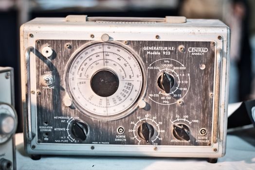
Cost: a CAT III 300 V loop tester with ±2% basic accuracy sits in the low-to-mid hundreds of USD/EUR list, while a Class 0.2S multifunction power meter with Modbus RTU is in the high hundreds to low thousands; a Class A IEC 61000-4-30 power-quality monitor is four-figure and upward. Lifetime: a hand-held tester sees five-to-ten years of light duty and then typically the test leads wear before the electronics; a panel-mount meter is rated for 10-20 years of continuous energisation. [S2]
Integration effort: a tester needs no integration — it is held against the test point and the reading is written on a clipboard. A meter needs a CT/PT pair correctly sized to the feeder (e.g. 800/5 A, 5 VA, Class 1 for a 400 A main), a Modbus address, a destination register map, and a SCADA poll cycle. Outputs: the tester prints or displays Zs in ohms and Ipf in amps, the meter streams V, I, kW, kVAr, kVA, PF, Hz, THD, and event logs every 1 s to 15 min. These four criteria (cost, lifetime, integration effort, outputs) let a buyer rank a list of vendors mechanically without sitting through a sales call.
Common failure modes and procurement traps
Loop tester traps: picking a 2-wire-only instrument and discovering during a re-test that no neutral is available at the test point; picking a CAT III instrument and being asked to test a point upstream of the main breaker; ignoring the test-current magnitude (high-impedance RCD-protected circuits need a tester that can drive the loop without tripping the RCD mid-test). These are not exotic failures — they show up in every EICR review that surfaces an out-of-tolerance Zs reading. [S2]
Power meter traps: under-sizing the CT (a 100/5 A CT on a 180 A feeder clips and silently bills wrong), mixing CT ratios on the same Modbus trunk, ignoring the meter's own auxiliary-power burden (a self-powered meter steals current from the measured phase, which is fine for billing but disturbs residual-current monitors on the same bus), and accepting Class 1 accuracy on a feeder that feeds revenue-grade tenants. Cross-check the meter's published burden on its datasheet; a 0.2S meter is meaningless if the CT chain it sits on is Class 3.
Where impedance and energy interact in the system
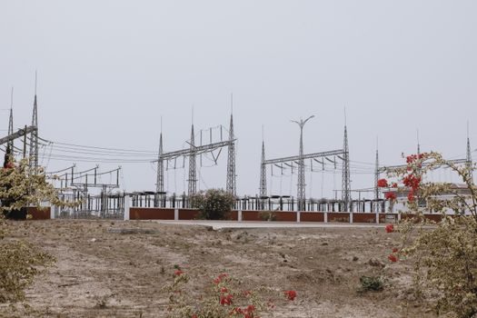
The IEEE work on impedance specifications for DC distributed power systems is not directly about mains-frequency loop testing, but it carries the same underlying principle: small-signal stability of a multi-module system is governed by the source-output to load-input impedance ratio Z<sub>o</sub>/Z<sub>i</sub> [S1]. Translated to a 50/60 Hz LV distribution, the practical takeaway is the same: define the source-side impedance, define the load-side impedance, and verify the ratio at the point of interconnection. That is what a loop tester does at handover, and that is what a power-quality monitor continues to do on the THD and flicker channels over the life of the installation.
For a deeper dive on the tester's wire count, test current, and CAT rating — the three numbers that decide the handheld — see this Loop Impedance Tester Selection: Wire Count, Test Current and CAT Rating walkthrough. For the meter side, a working loop calibrator on the test bench is the only reliable way to prove the 4-20 mA loop feeding the meter's analog output card stays inside its published accuracy, and a deadweight tester covers the pressure side of the same instrument air supply if the meter lives in a hazardous-area enclosure. Buyers specifying both should write the tester spec and the meter spec in the same procurement document so that the CT chain, the comms chain, and the test-point access are designed together, not bolted on later.