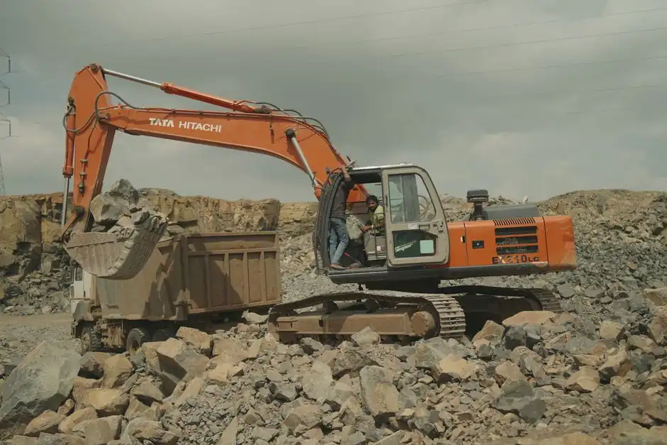
A load-holding (counterbalance) valve sits on the extend port of each double-acting cylinder on a lorry-mounted crane, performing three duties: controlling the rate of decent, keeping the load from falling if system pressure is lost, and acting as a relief valve against induced or thermal-expansion loads [S2].
It is described in OEM literature as a pilot-assisted relief valve with a free-flow check, fitted between the directional control valve and the cylinder rod end on a typical PTO-driven, open-center hydraulic circuit [S4]. The same cartridge architecture governs outrigger, boom-extend, and luffing cylinders on most truck loader cranes; the principles do not change between knuckle-boom and telescopic configurations.
Three Engineering Functions of the Load Holding Cartridge
Load holding is the primary safety duty: the poppet design limits cylinder drift to near zero, so a suspended load stays put when the directional valve is centered and no pump flow is commanded [S3]. On a lorry crane this is the difference between a parked boom and a dropped boom over a roadway or a worker.
Load control is the second duty, and it is the one operators feel most directly. When the crane lowers a load, gravity adds to the cylinder force, so the load tends to run ahead of pump flow; the counterbalance valve meters oil out of the rod end and prevents pump cavitation or runaway [S4]. Liftmoore specifies the cartridge on every extend port for this reason, freeing the directional valve from having to throttle descent [S2].
Load safety, the third duty, is the failure-mode function. If a hose ruptures or the PTO pump loses drive, the pilot-assisted poppet closes and locks the cylinder in position; a separate pilot-operated check on the retract port prevents creeping out under no load [S2]. This dual-valve logic is also why marine deck-crane diagnostics call out counterbalance health separately from cylinder-seal leakage when boom drift is observed [S5].
Circuit Position and Pilot Logic on a Truck Loader Crane
Standard placement is line-side, between the directional control valve and the rod end of the cylinder, so the cartridge can meter return oil during the lower cycle while the free-flow check lets oil pass unimpeded during the lift cycle [S4]. On the Liftmoore-style manifold the proportional flow control, the 2800 psi system relief, and the cartridge are stacked in a single block fed by a differential pressure sensing valve, so all functions share the same pilot supply [S2].
Pilot ratio is the parameter that decides whether the valve will open smoothly or jerk on command. The pilot line senses pressure on the bore (retract) side; once that pressure multiplied by the pilot ratio exceeds the spring setting on the rod-end cartridge, the poppet opens and the load can descend [S4]. Field service manuals therefore recommend adjusting the cartridge setting, not the relief valve, when an operator reports a stalled lower or a too-fast lower, and they warn that the cartridge must be re-set to nameplate after any emergency lower [S2].
On truck loader cranes sized for 20-30 tm work, the cylinder bores and rod diameters are large enough that a wrong pilot ratio produces visible boom bounce during feathering, a symptom easily confused with air entrainment or a sticky directional valve spool [S5]. The diagnostic shortcut is to isolate the cylinder and watch for pressure equalization across the cartridge: equal pressure means the poppet is bypassing; unequal pressure points at the directional valve or the pump.
Selection Criteria: Pilot Ratio, Cracking Pressure, and Capacity
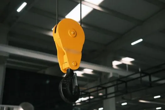
Three numbers drive a correct counterbalance spec: pilot ratio, cracking pressure, and rated flow. Pilot ratio, the ratio of bore-end area to poppet area, is commonly offered in bands around 1.5:1 to 10:1; a higher ratio opens the valve at lower pilot pressure but reduces the metering stiffness, while a lower ratio holds the load harder at the cost of higher pilot pressure demand [S3].
Cracking pressure is the spring setting that the rod-end pressure must overcome to allow flow out of the cylinder; it is normally set above the maximum load-induced pressure at the rod end so the valve stays shut at rest. On a lorry crane, this value has to be re-checked after any boom-extension change, because adding a section changes rod-end volume and therefore the load-induced pressure that the cartridge sees [S2].
Rated flow must match the cylinder's maximum extension speed at full pump delivery. A cartridge that is undersized for flow will chatter and erode; one that is grossly oversized will not meter low-flow fine control well, which is the regime that operators use to place a load. Vendor cut sheets normally list a flow-versus-pressure drop curve; the operating point should sit in the middle of the curve, not at either end. For a more general view of how loader cranes are sized and paired with carriers, see the 20 tm vs 30 tm lorry loader crane trade-off.
Failure Modes and Field Diagnostics
Cylinder drift at rest is the most common complaint and the most often misdiagnosed. A leaking counterbalance valve, a bypassing directional valve spool, and thermal expansion of the trapped oil can all move a parked boom; piston-seal leakage is only one of the possibilities [S5]. The correct first move is to command the function, center the directional valve, and watch the gauge on the rod-end line: a steady pressure drop on the rod side, with a steady pressure on the bore side, points at the cartridge; a drop on both sides points at the cylinder or the directional valve.
Jerky motion during feathering is the second most common complaint and is usually blamed on the wrong component. Air entrainment, varnish on the directional spool, and an unstable counterbalance pilot all produce the same shake, so the diagnostic order is: check fluid cleanliness to ISO 4406, sample for water, then verify pilot pressure stability at the cartridge port [S5]. Cold oil raises viscosity and mimics a weak pilot, so warm the system within OEM spec before any conclusion is drawn.
Free-fall on hose failure is the failure mode the cartridge is designed to prevent, and it is the one that drives most of the safety-case work. Forensic investigations of mobile-crane tip-overs routinely find a missing or mis-adjusted counterbalance, a cracked pilot line, or a cartridge that was replaced with a non-equivalent part during a previous service [S1]. Warren Forensics' published casework treats the cartridge as the single component most likely to be overlooked when assigning root cause, because the boom does not move during a post-incident teardown until the lines are repressurized.
Standards, Service Intervals, and Safety Baseline
Marine and offshore deck-crane practice, captured in ISO 4413 for general hydraulic safety and in class guidance such as DNV ST-0377 for shipboard lifting appliances, sets the documentation baseline: lock out, depressurize, chock the load, and verify residual pressure is vented before any cartridge is removed [S5]. The same baseline, adapted to road-going lorry cranes, is the only defensible posture for roadside service.
Service intervals on the cartridge itself are not calendar-based; they are condition-based. Contamination targets expressed as ISO 4406 codes (commonly in the 18/16/13 class for mobile hydraulics) protect the poppet seat, while case-drain flow trending against the OEM baseline catches internal pump wear before it shows up as counterbalance instability [S5]. Hose life is the other variable: every hose on the lift circuit has a fixed flex life and is the first component to fail in a well-maintained system, so the counterbalance must be assumed to be the last line of defense and inspected on that basis [S3].
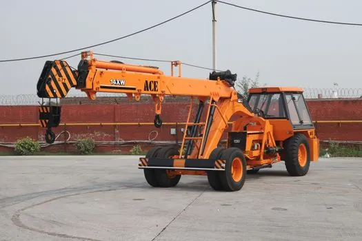
For context on how the cartridge interacts with the rest of the hydraulic package, the truck-mounted crane encyclopedia page covers the broader machine architecture, while the hydraulic valve page covers cartridge families, pilot stages, and the relief/check/counterbalance distinctions that show up on a real schematic.
When a Load Holding Valve Is the Wrong Choice
A counterbalance is not always the right block. On functions that need to free-fall under gravity for emergency release, such as some winch designs, a counterbalance is omitted by design and a different safety case is built around the brake. On very low-load hold functions, such as small outrigger pads, a simple pilot-operated check is cheaper and adequate; the trade-off is no metering on the lower stroke, which is acceptable because the load is light and slow. [S4]
A load-holding valve is also the wrong fix for a system that has the wrong pump, undersized lines, or a directional valve with internal leakage. Installing a stiffer cartridge on top of a bypassing directional valve only delays the failure and can mask it from the operator. The right sequence is: prove the pump, prove the directional valve, prove the lines, then specify the cartridge.
For lorry loader cranes specifically, the rule of thumb is to put a cartridge on every extend port of every load-bearing cylinder, plus a pilot-operated check on the retract port of any cylinder that can creep out under no load, and to keep the system relief within roughly 10% of the OEM nameplate setting [S2]. Deviating from that pattern is the most common root cause behind the drift and free-fall cases that show up in forensic files [S1].
Next signal to track: any revision to ISO 4413 or to the EN 12999 lorry-loader safety standard that tightens pilot-ratio documentation requirements, and any OEM service bulletin that ties counterbalance cracking pressure to boom-extension section count. Both would force a re-spec of the cartridge on machines that have had their booms lengthened in service, and both are worth watching through 2026 as more truck loader cranes are retrofitted for higher-capacity duties.
For component-level specifications, see function generator.