
Full outrigger spread, ground bearing capacity, and a defined working arc are the three engineering numbers that decide whether a truck-mounted crane lifts at rated capacity or fails [S1][S2].
The vehicle is rated stable only when the hydraulic stabilisers unload the rear tyres, the boom operates inside the certified work area, and the load stays under the SAE J765 stability test envelope of 118% of rated capacity (85% of tipping load) [S1].
Stability test rules: SAE J765 and OSHA 1910.180
Stability testing of a service crane on a truck chassis is performed at 118% of maximum capacity, equivalent to 85% of the calculated tipping load, around the full rotational arc per SAE J765, Crane Load Stability Test Code [S1]. OSHA CFR Part 1910.180 (C)(1) is the binding US requirement for installer compliance, and the legacy 110% OSHA test limit was removed from the standard because it applied to structural repair replacement, not stability proof [S1]. The test demands a hard, level surface within +/- 1% grade, full horizontal outrigger extension, jack legs extended until the outrigger cross-tube contacts the top of the outer tube (tyres unloaded but not lifted), and boom elevation between 0-15 degrees at the worst-case "B" position [S1]. If the test weight cannot be lifted clear of the ground by approximately 6 inches, the vehicle is unstable and engineering must be consulted [S1].
Outrigger spread physics and ground bearing pressure
Outriggers shift the tipping axis outward from the truck's centre of gravity, increasing the resisting moment that counters the load moment and reducing the vehicle's tendency to overturn [S2]. The load path bypasses the rubber suspension entirely: hydraulic cylinders push against the earth, the tyres unload, suspension energy is bled off, and 100% of the operational force passes through the steel legs into the ground [S2]. Static stability is a solved problem; dynamic stability is where failures occur, because swinging loads, wind, and quick slewing inject lateral momentum that the outrigger frame must absorb [S2].
Ground bearing pressure (GBP) is the limiting number on real sites. Dense sand and gravel tolerate 200-300 kPa of safe contact pressure, firm clay tolerates 100-200 kPa but softens after rain, and loose fill or topsoil only tolerates 50-100 kPa before settling [S4]. On any soil class below firm clay, outrigger mats or steel pads must be placed to enlarge the contact area and keep contact stress below the soil's safe GBP [S4].
Stabiliser types, leveling, and site preparation
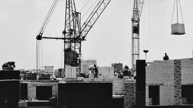
Hydraulic stabilisers have largely displaced mechanical parking jacks on modern loader cranes because they compensate for ground irregularities, distribute weight evenly to keep ground pressure low, and integrate safety valves to prevent uncontrolled retraction [S3]. The two configuration families are parking jacks (manual, locking) and hydraulic stabilisers (rapid, precision, ground-compensating), with the hydraulic variant being the prevalent choice on construction and industrial sites requiring high safety standards [S3]. Site preparation is non-negotiable: ground must be firm and level, stabilisers fully extended per manufacturer guidance, and the unit re-leveled after outrigger deployment and again after a test pick [S3][S4].
On a related chassis decision, the 6x4 vs 8x4 loader crane chassis comparison is the upstream choice that constrains how wide an outrigger spread a given truck can physically carry and still meet route and axle-load regulations.
Electronic stability control: multiple zones, one crane
European-market cranes with a lifting capacity of at least 1000 kg or a lifting moment of 40,000 Nm or more must integrate vehicle stability control into the moment-limiter function per EN 12999:2011 and the Machinery Directive 2006/42/EC [S5]. Fassi Stability Control (FSC) reads the deployment state via two devices: a proximity sensor that confirms ground contact of the stabiliser jack, and a micro/encoder reel that measures the extension of the lateral outrigger support [S5]. The crane will not authorise operation until both conditions are met on both sides.
FSC tiers stack capacity maps onto a single machine. FSC/L checks only that lateral extensions are fully deployed on both sides. FSC/M adds right-versus-left working-area recognition and a differentiated moment limiter that allows maximum capacity over the truck bed but reduced capacity over the cab. FSC/H expands the outrigger reading positions from 3 (M2) up to 5 for the crane plus 3 for an additional crossbeam, unlocking up to 10 different crane performance levels, each matched to a verified outrigger configuration [S5].
Working zones, LMI, and the boom arc
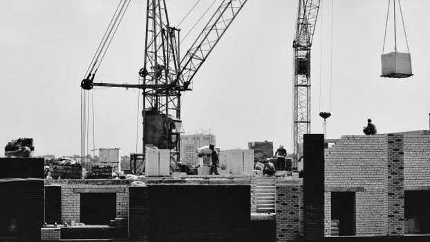
A stability zone is the geometric envelope inside which a given combination of outrigger spread, jack deployment, and boom configuration will hold the load without exceeding the 85% tipping-load safety margin [S1][S5]. Load Moment Indicators (LMI) and interlocking deployment sensors enforce the zone: the operator cannot command a lift outside the envelope the system has authorised, which is the engineering answer to short-rigging errors [S2].
Comparison of the three main stabiliser-deployed operating modes against decision criteria:
Mode A: full outrigger spread, jacks fully deployed, all tyres unloaded. Highest capacity, full 360-degree arc, required for any lift above reduced-capacity thresholds. Ground requirement: 100-200 kPa safe GBP minimum (firm clay or better) [S1][S4].
Mode B: partial outrigger spread, one side retracted (FSC/M and below). Reduced capacity, restricted working arc on the retracted side. Used where the site physically blocks full extension, with mats on the deployed side taking the higher per-pad load [S2][S5].
Mode C: stabilisers retracted, only parking jacks or short stabilisers, boom restricted to rear arc. Lowest capacity, narrowest zone. For utility lifts on prepared hardstand where full outrigger deployment is impossible [S3].
Failure modes and inspection discipline
Stability failures cluster around three causes: outrigger short-rigging (operator deploys partial spread and ignores the LMI), inadequate ground (no mat used on soft soil, settlement tilts the chassis), and dynamic overload (swinging load or rapid slewing pushes the moment past the 85% tipping threshold) [S2][S4]. Pre-lift inspection must cover outrigger beams, hydraulic cylinders, housings, and corrosion on load-bearing welds, plus pad sizing matched to the soil class [S4]. Chassis and outrigger alignment, leveling capability, and control responsiveness are checked before extension, not after the boom is already loaded.
For projects where stabiliser footprint interacts with foundation work, the construction machinery and equipment category covers the wider rigging and ground-prep tools that show up alongside a deployed crane. A lorry-mounted crane at full outrigger spread is mechanically a different machine from one at retracted stabilisers, and the rated capacity, arc, and LMI envelope all change with it.
Two trackable signals to watch: harmonisation of EN 12999:2011 revisions for cranes with stabiliser management tied to ground-contact sensors, and broader LMI integration with machine telemetry so deployment state is logged rather than trusted to the operator. Both will tighten the audit trail between a decal on the truck and the actual spread on the ground at lift time.
For the relevant spec sheets and selection criteria, see truck mounted concrete pump.