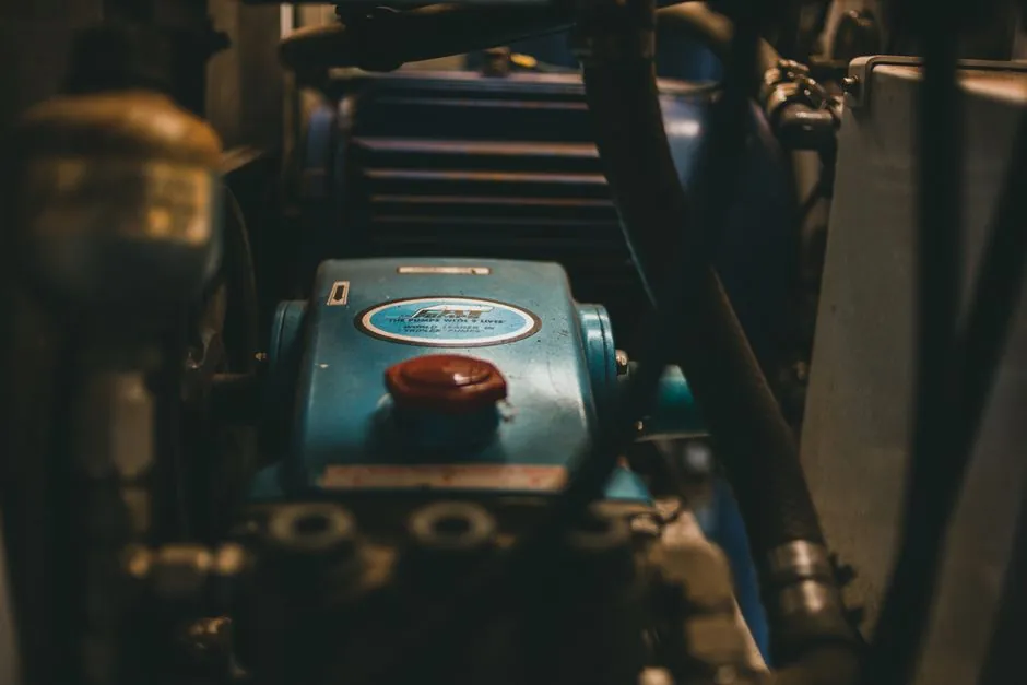
Magnetic drive pumps differ from mechanical-seal pumps in three installation-critical ways: the magnetic coupling transmits torque across a non-contact gap, the bearings are fluid-lubricated by the process medium, and the containment shell separates the wet end from the atmosphere [S2][S7].
Treating a mag-drive pump like a conventional ANSI B73.1 seal pump is the single most common root cause of premature failure; in one 47-installation audit, 68% of premature bearing failures were traced back to inadequate foundation work, not pump quality [S1]. Flow range, head, and materials vary widely: 1–500 L/min (0.26–132 GPM), up to 25 bar (362 psi), with casings in PP, PVDF, SS 316, or Hastelloy and magnets in samarium cobalt (SmCo) or neodymium configurations [S3].
Foundation, Grout, and Site Geometry
Non-shrink, epoxy-modified grout meeting ASTM C1107 Type III with compressive strength ≥12,000 psi at 28 days is the minimum foundation spec; a 3-inch minimum depth under the baseplate, verified with rebound hammer testing, is the standard that separates passing installs from chronic vibration [S1]. A documented failure case: a 150 gpm hydrofluoric-acid transfer pump vibrated at 7.2 mm/s RMS after four months when grout was skipped, with micro-cracks absorbing resonance energy instead of transmitting it to the foundation [S1]. The floor must slope 1/8" per foot away from the pump base; stainless steel trench drains with 304 SS grates (not PVC) catch any containment-shell seepage that otherwise saturates grout and lifts the baseplate [S1].
Magnetic couplings lose roughly 3.2% of transmitted torque per °C above 80°C, so when ambient exceeds 35°C or radiant heat sources sit within 1.5 m, thermal break pads such as Glastic TBP-200 under the mounting feet are the standard countermeasure; a nitric-acid service pump in Arizona saw surface temperature drop from 58°C to 41°C with this fix, extending coupling life 3.7x [S1]. Pump bases are installed horizontally, not vertically, and the plastic or lined pump casing must never carry pipeline weight; for the rare vertical-mount case, motor-up is the only accepted orientation [S2].
Alignment Tolerances and Laser Procedure
Mag-drive pumps require ≤0.0015" total indicator reading (TIR) at the coupling face, roughly three times tighter than the 0.005" TIR commonly accepted on mechanical-seal pumps, because axial thrust on the internal magnet assembly creates harmonic torsional vibration that amplifies any misalignment exponentially [S1]. The accepted field sequence: pre-load baseplate bolts to 70% of spec torque per ASTM F2432, loosen only the four corner bolts, then run laser alignment at 0°, 90°, 180°, and 270° (not just two points) because mag-coupling harmonics shift phase at 120° intervals [S1].
Correction uses shim stacks only; jacking screws induce point-loading that warps the baseplate, while aluminum shims creep under thermal cycling, so 0.001"-thick stainless shims to AMS 5504 are the standard [S1]. Re-check alignment at three checkpoints: after 24 hours when grout settles, after the first hot cycle, and document all three readings in a signed log per ISO 5199 Annex B [S1]. For a primer on magnetic drive pump operating principles that drive these alignment choices, the encyclopedia entry covers coupling geometry and torque transfer.
Piping, Suction Conditions, and Priming
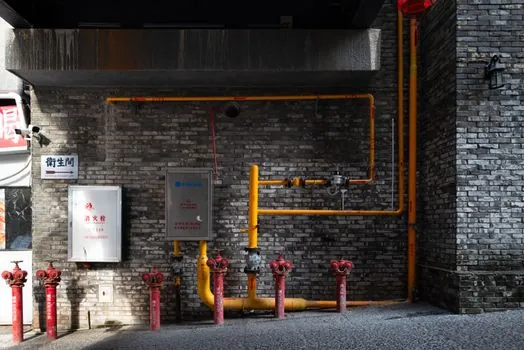
Suction pipe diameter must equal or exceed the pump suction inlet; non-collapsible hose or rigid pipe is required, and every fitting must be airtight because any air ingress drives cavitation that damages the internal magnet assembly [S5]. When the suction liquid level sits above the pump axis, open the suction valve before starting; when it sits below, install a bottom valve to keep the suction leg primed [S2]. Discharge piping diameter should also equal or exceed the pump discharge, which keeps friction loss low and protects the head curve from dead-heading damage [S5].
Discharge valve must be opened slowly after the motor starts, and adjusted to the required flow only after the pump reaches normal working state [S2]. Closing the downstream isolation valve while the pump runs overheats the pump head and may damage internals, so the operating procedure rule is: never throttle on the discharge while running [S5]. If the process medium carries solid particles, install a filter at the inlet; if it carries ferromagnetic particles, add a magnetic filter upstream to protect the coupling [S2].
Electrical, Dry-Run Protection, and Commissioning
Dry running is absolutely prohibited on magnetic drive pumps because the bearings depend on the pumped medium for cooling and lubrication; even a brief idle period causes bearing damage, and any restart after a mid-process power failure must wait until the pump is fully flooded again [S2]. To safeguard against this, the minimum control package on every mag-drive install is a low-flow or loss-of-prime cutoff wired into the motor starter; for the same reason, gauges on inlet and discharge, plus an inline flow meter, are specified so trends are visible before a failure event [S5].
Motor rotation must match the steering mark on the pump before first start; the motor fan should spin freely with no rub or abnormal sound, and every fastener must be torqued to spec [S2]. Ambient temperature during operation must stay below 40°C, and motor winding temperature rise must not exceed 75°C, per the same OEM installation guide [S2]. For services that handle flammable, volatile, explosive, or toxic liquids, the pump should be specified to ASME B73.3-2003, the sealless pump standard covering exactly these media, and grounded to dissipate any static buildup during transfer [S2][S5].
Material and Pressure Limits by Build

Engineering-plastic mag-drive pumps (PP or PVDF wetted path) are limited to a service temperature below 60°C and a working pressure up to 0.2 MPa (with a 1.6 MPa maximum allowable); metal mag-drive pumps (SS 316, Hastelloy, or titanium containment shell) extend the service ceiling to 100°C and hold the same 1.6 MPa maximum working pressure, with conveyed medium density capped at 1600 kg/m³ [S2]. Where aggressive chemistry rules out standard alloys, Hastelloy or titanium isolation sleeves are the standard upgrade, manufactured as fully sealed structures that drain completely during shutdown and vent automatically during pre-startup priming [S7].
For processes that demand higher pressure or flow, high-capacity models reach 500 L/min and 25 bar, and the magnet selection shifts to SmCo for thermal stability or neodymium where raw torque density matters more than high-temperature margin [S3]. When the question is material selection for stainless-steel wet ends in PCB or pharmaceutical ultrapure water, an SS magnetic drive pump selection guide lays out the alloy-and-finish trade-offs that drive the casing choice. The containment-shell material also dictates the pump's compatibility with corrosive or hazardous media: a typical mag-drive uses a static seal where a conventional pump uses a dynamic seal, so the flow path stays fully enclosed [S10].
Acceptance Criteria and When to Escalate
Acceptance at commissioning is conditional on three documented checks: (1) vibration velocity under 4.5 mm/s RMS at the bearing housing during the first hot cycle, (2) containment-shell surface temperature at or below 80°C under rated load (above this, coupling torque loss accelerates and demagnetization risk rises), and (3) zero visible seepage at the static seal after a four-hour full-flow hold [S1][S2]. If any of these fail, the corrective action is to re-verify grout integrity with a rebound hammer, re-shim to ≤0.0015" TIR with a fresh set of AMS 5504 stainless shims, and re-document per ISO 5199 Annex B before re-energizing [S1].
Escalation to replace rather than repair is the right call when the containment shell shows any crack, when bearing-housing vibration exceeds 7.2 mm/s RMS (the level that one pharma client recorded four months after a skipped grout step), or when the magnet assembly has been run dry for any measurable period, since dry-run damage is not reversible by re-alignment alone [S1][S2]. For the related decision of shaft and coupling material grades used in pump rebuild shops, the sand-blasting machine selection for pump and valve production reference covers the surface-prep side of a teardown-and-rebuild workflow. The next trackable signal is the operator's first 72-hour vibration trend: a flat baseline below 3 mm/s RMS confirms the alignment discipline held, while any upward drift above 4.5 mm/s is a flag to re-shim before the next service interval.
Spec-level background on the components involved: linear guide.