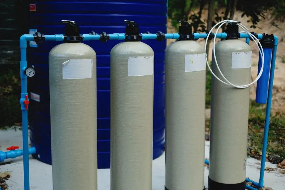
A multistage centrifugal pump stacks 2 to 12 impellers in series inside one casing, and each stage adds 50 to 200 psi (3.5 to 14 bar) of head to the fluid, letting the assembly reach total heads up to 1,500 m and flow rates from roughly 1 m³/h to 1,500 m³/h [S2][S8].
The technology covers a wide power band, 0.75 kW to 2,500 kW (1 HP to 3,350 HP) on 2-pole frames, and is most commonly specified for boiler feed, reverse osmosis (RO) feed, high-rise water supply, and pipeline boosting rather than slurry service [S8][S10].
Working Principle and Mechanical Build
A multistage centrifugal pump contains two or more impellers on a single shaft inside one housing, with each stage acting as a separate pump that adds energy to the fluid [S4]. The motor spins the shaft, fluid enters the first impeller, and guide vanes redirect the flow into the next stage, where its kinetic energy is converted into additional pressure before discharge [S3].
Stacked impellers multiply the cumulative axial thrust on the shaft, so quality builds include a balance drum or balance disc plus robust casings rated for the working pressure [S7]. Standard stage counts run from 2 to 12, with up to 8 stages typically placed on a single horizontal shaft before designers move to multi-shaft configurations [S3][S4].
Head, Flow, and Efficiency Envelope
Industrial multistage units can reach 1,500 m (4,921 ft) of head, with pressure ratings documented up to 5,000 psi (about 345 bar) in high-pressure series, and 800 to 3,000 psi (55 to 200 bar) is the working window for boiler feed service [S2][S8]. Flow rates in commercially available frames stretch from about 1 m³/h (4.4 GPM) for small RO boosters to 1,500 m³/h (6,600 GPM) for large cooling-water and irrigation units [S8].
Closed-impeller designs on well-matched systems reach 75% to 85% mechanical efficiency, and the staged architecture keeps flow constant through every stage while head adds up stage by stage [S3][S4]. Compared with a single-stage pump, the multi-stage unit outperforms on high head but loses efficiency on high-flow, low-head duty, which is the operating point where single-stage end-suction or double-suction pumps become the cheaper pick [S2].
Selection Criteria: Match Head, Fluid, and Footprint
Start with total dynamic head (TDH): overspeccing stages wastes energy and inflates maintenance, so size the stage count to the calculated head rather than picking the largest frame available [S9]. Fluid properties are the second gate; multistage pumps handle water-like fluids well but should be limited to roughly 500 cP, and any abrasive or fibrous media will accelerate impeller wear [S2].
Footprint drives the third decision: horizontal split-case is the easiest to maintain, ring-section designs bolt together for modular high-pressure work, and vertical turbine formats fit deep wells and RO skids where floor space is tight [S2]. For chemical or mildly corrosive service, stainless steel wetted parts in 304 or 316L are the default material upgrade, with closed-impeller geometry preserving the 75% to 85% efficiency band [S3].
Where Multistage Wins vs Where It Loses
Multistage pumps win on high-pressure, low-to-medium flow duty: boiler feed (800 to 3,000 psi), RO feed (200 to 1,200 psi), oil and gas pipeline boosting (500 to 1,500 psi), and high-rise HVAC supply (150 to 600 psi) [S2]. On slurry, viscous fluid, or dirty water service, single-stage or positive displacement designs are the safer pick because multistage impellers and close guide-vane tolerances cannot tolerate solids or fluids above roughly 500 cP [S2][S4].
Compared with positive displacement (PD) pumps, multistage units deliver smoother, less pulsating flow and beat PD pumps on efficiency at high flow with low-viscosity water-like media, but they trail PD on high-viscosity and high-pressure slip-sensitive duty [S2]. Compared with a single-stage centrifugal, the multi-stage trade is higher first cost and more seals, in exchange for compact high-pressure output and better part-load efficiency on high-head systems [S2].
Configuration Comparison: Horizontal, Vertical, and Ring-Section
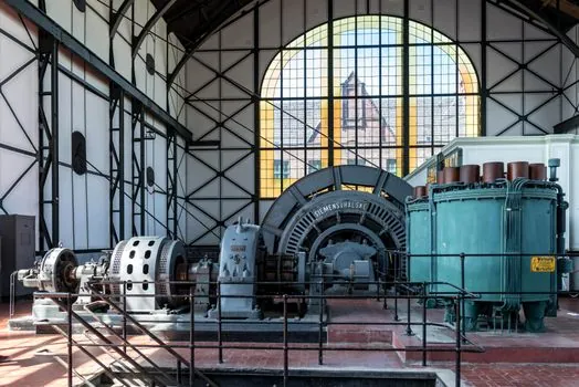
Horizontal multi-stage pumps place impellers on a horizontal shaft in a segmented casing, with up to 8 stages typical, and they dominate boiler feed, high-pressure washing, and industrial water supply [S2][S4]. Vertical multi-stage designs (VS4, VS6 styles) stack impellers in a vertical column for deep wells, RO skids, and cooling-water circulation, fitting where a horizontal footprint is impractical [S2].
Ring-section designs bolt modular stages together for compact high-pressure builds and are common in firefighting and clean-water high-pressure service [S2]. For a deeper pump-type cross-cut, see the multistage pump selection reference, and where duty shifts to abrasive or viscous fluids, the diaphragm pump family fills the gap that a multistage cannot cover. If you are benchmarking against reciprocating alternatives on the same head, the plunger pump spec gate guide gives a useful side-by-side on pressure, viscosity, and maintenance.
Failure Modes, Maintenance, and Misconceptions
The cumulative axial thrust from every stage is the dominant mechanical risk; if the balance drum, balance disc, or thrust bearing is undersized or worn, the shaft walks and the mechanical seal fails prematurely [S7]. Cavitation, overspeed on cold starts, and running far from the best-efficiency point (BEP) all drop closed-impeller efficiency below the 75% to 85% benchmark and accelerate wear rings, so operators should always check NPSH margin before commissioning [S3].
Maintenance intensity is often overstated: modern horizontally split multistage designs let technicians inspect internals without breaking the process piping, so routine service is comparable to a single-stage pump once the seal plan is right [S9]. A more useful procurement check is matching stage count to calculated TDH; an extra stage beyond system head is wasted energy and an extra seal to maintain, with no benefit to the process [S9].
Sourcing Notes, Standards, and Trackable Signals
Material and seal specs should be pinned to the fluid, not the brand: stainless 304/316L wetted parts, EPDM or Viton mechanical seals, and API 610 or ISO 5199 alignment for refinery and boiler-feed builds are the safe defaults; for general water-service frames, CE conformity and ISO 9906 hydraulic acceptance testing are the usual reference points. Catalog frames from manufacturers such as Frigate cover 0.75 to 2,500 kW at 2-pole speeds, and well-known reference series include Grundfos CR, Sulzer HPH/MSD, KSB Multitec, and Flowserve OHx (API 610) [S8][S2].
Track the next decision by pulling the fluid's viscosity, TDH, and required flow into a single datasheet before talking to vendors, then verify each candidate's published head curve sits at or above your duty point with at least 10% margin. If your service moves toward abrasive or fibrous fluids, a multistage stops being the right tool; switch to a slurry or PD design and revalidate the head and viscosity envelope against the same datasheet. For procurement teams lining up castings and machined parts across pump and valve lines, the sand-blasting machine selection reference is a useful adjacent read on surface-finish gates that complement pump-component QA.