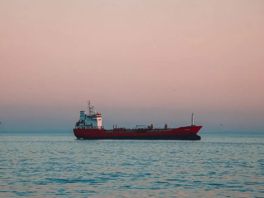
Select a marine balancing valve by matching nominal circuit flow to the valve’s published flow range, then verify differential-pressure capability, pressure rating, material, and installation limits.
The supplied Hays Mesurflo material lists bronze and stainless-steel models beginning at 1/2 in., with capacities from 0.50 to 120 GPM and operating differential pressures up to 80.0 PSID [S2].
Marine balancing duty and valve architecture
A balancing valve controls flow through a marine circuit, but the correct architecture depends on whether the design flow is stable or changes with operating demand. Manual valves are adjusted during commissioning and remain fixed, while automatic valves maintain a selected differential pressure as system conditions vary [S1].
Manual valves divide into two operating principles. A fixed-orifice valve retains one internal flow geometry between its pressure-test ports and relates differential pressure directly to flow using Q = Cv√ΔP. A variable-orifice valve changes its effective Cv as the knob moves, so commissioning requires the manufacturer’s curve family for each valve size and knob position [S1].
Automatic balancing is the stronger choice for marine circuits exposed to pump changes, load variation, or frequent operating changes. Manual balancing remains economical for stable auxiliary loops where commissioning access is dependable. A broader comparison with non-marine process applications appears in Balancing Valve Selection for Oil and Gas Systems.
Size from design flow, not pipe diameter
Size a balancing valve from the required nominal flow and its allowable pressure drop. Pipe diameter only establishes the connection envelope; it does not guarantee that the installed valve can pass or accurately control the design flow [S4][S5].
For variable-orifice valves, record both knob position and differential pressure before interpolating toward the target flow [S1].
Compare manual, automatic, and preset balancing valves
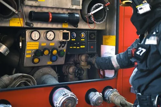
Manual balancing valves provide low-cost, hands-on control for stable circuits, but they require measurement and repeated adjustment. Automatic balancing valves add a diaphragm or actuator that responds to differential pressure, making them better suited to variable marine demand [S1][S2].
Marine flow ranges and pressure-drop envelopes
Published capacity, not nominal line size, determines whether an automatic marine valve can perform its duty. Hays Mesurflo bronze models cover 1/2 to 2-1/2 in. nominal sizes, while the supplied stainless-steel models include 1/2 to 1-1/2 in. nominal sizes and capacities beginning at 0.50 GPM [S2].
Model 2313 in 1/2 in. handles 0.50 to 5.00 GPM at 3.0 to 80.0 PSID, while the 3/4 in. version handles 5.50 to 9.00 GPM at 4.0 to 80.0 PSID. Model 2333 in 1-1/2 in. covers 26.0 to 50.0 GPM at 5.0 to 80.0 PSID, and Model 2335 in 2-1/2 in. covers 50.0 to 120.0 GPM at the same differential-pressure band [S2].
Pressure, temperature, materials, and installation constraints
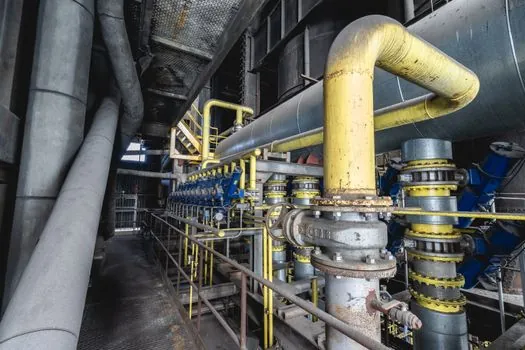
Marine service requires the pressure and temperature rating to cover the circuit, including fill pressure, static head, thermal expansion, and pump operating conditions. Victaulic TA Series 786H, 787H, and 78KH are rated to 400 psi, Series 789 to 350 psi, and Series 788 to 250 psi [S3].
Victaulic lists sizes from 1/2 to 16 in., equivalent to DN15 through DN400. Series 786H, 787H, and 78KH operate from -4°F to +248°F, or -20°C to +120°C. Series 788 and 789 operate from +14°F to +248°F, or -12°C to +120°C [S3].
Material selection must consider the marine medium and exposure.
Automatic valves should not be selected when the available differential pressure can fall below the published operating minimum, such as 3.0 PSID for one Model 2313 range or 5.0 PSID across most listed Mesurflo capacities [S2]. Manual valves should not be selected where flow changes without an operator available to rebalance the circuit [S1].
Commissioning and acceptance criteria
Commission the selected valve against measured flow rather than pipe size, wheel position, or pump capacity alone. Establish the circuit’s available differential pressure, measure the pressure drop across the balancing device, and calculate or read the corresponding flow from manufacturer data [S4][S5].
For automatic valves, verify that the selected operating point lies within the manufacturer’s flow and differential-pressure windows. Model 2545SS uses 50 to 100 GPM in 1 GPM increments and 105 to 225 GPM in 5 GPM increments, both at 5.0 to 80.0 PSID [S2]. These defined capacities make preset selection more precise than accepting any point between broad minimum and maximum limits [S5].
For manual valves, use pressure-test ports and a suitable differential-pressure instrument. A programmable digital manometer can convert measured differential pressure to flow for fixed-orifice units [S1]. Variable-orifice units require the manufacturer’s curve family, and the acceptance record should include the final differential pressure, indicated flow, knob position, and date.
Confirm accessible measurement ports, isolation capability, a lockable or memorable preset, and sufficient straight pipe or installation geometry required by the selected valve before purchase [S4].
Build the procurement shortlist from three checks: nominal flow falls inside the selected model’s capacity, required differential pressure remains within its operating envelope, and body material and pressure class suit the marine circuit. Add any candidate article on Marine Ball Valve Selection: Body, Bore, Class, and Compliance to the review only if the system also requires ball-valve isolation, but do not confuse a general isolation valve with a balancing valve.