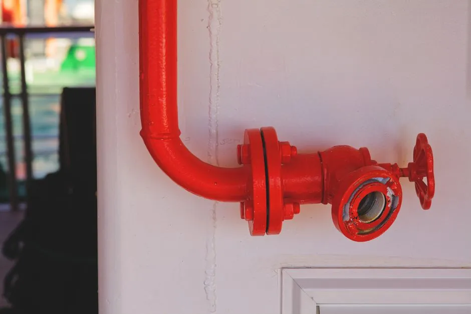
Marine safety relief valve selection starts with the protected system and fluid, then confirms set pressure, required relieving capacity, allowable back pressure, temperature, corrosion resistance, and marine class approval.
Conventional relief valves modulate for liquid service, safety valves pop rapidly for compressible service, and safety relief valves combine both operating characteristics for liquid, steam, or gas duties [S2].
Match valve action to marine service
ASME defines relief valves, safety valves, and safety relief valves under the Boiler and Pressure Vessel Code (BPVC) [S2]. Marine installations can also require naval or classification-society approvals, so the governing code set must be identified before ordering.
A pressure relief valve opens in proportion to pressure above its set point and is suited to liquid systems [S2]. A safety valve provides rapid, full-lift pop action and is suited to steam and gas systems [S2]. A safety relief valve is acceptable across liquid, steam, or gas service because it combines gradual and rapid opening characteristics [S2].
Use the safety relief valve terminology only when the certified valve meets the required definition for the selected service. In marine work, the procurement document should identify the valve type, governing code, classification requirements, test basis, and whether the device must operate without an external power source [S5].
Build the sizing basis before selecting construction
Relieving capacity is the flow the valve must discharge at the specified set pressure and overpressure, not a generic flow rating [S4][S5]. The sizing process must define the protected equipment, design and operating pressures, fluid properties, credible overpressure scenario, required relieving capacity, allowable accumulation, inlet pressure loss, and discharge back pressure [S3][S5].
For steam service, the calculation sequence is to establish required relieving capacity, calculate set pressure, select the applicable sizing equation, and calculate the required valve size [S3]. The finished selection must retain enough margin to cover the selected orifices rather than choosing from connection size alone [S4].
Relief valves are not pressure regulators; their primary purpose is to protect life and property by venting fluid from over-pressurized vessels, lines, and systems [S5]. Pressure relief is distinct from pressure regulation, so a separate pressure-control strategy is needed where regulation is required [S5].
Compare the principal valve types

The comparison is driven by fluid behavior, opening mode, and service suitability. A conventional relief valve provides proportional opening for liquid service; a safety valve provides rapid pop action for steam or gas; and a safety relief valve accepts liquid, steam, or gas service but does not automatically resolve a marine-specific back-pressure or certification problem [S2].
Connection size and type must match the inlet and discharge piping, with threaded or flanged arrangements considered during procurement [S4]. Conventional and non-conventional devices may be combined with rupture disks, but the training material used for this guide treats rupture discs separately from pressure relief valve sizing [S5].
Set pressure and overpressure need explicit limits
A relief valve must open at a predetermined set pressure, deliver rated capacity at a specified overpressure, and close after system pressure returns to a safe level [S5]. The set pressure therefore cannot be selected from the vessel nameplate alone; normal operating pressure, maximum allowable accumulation, system dynamics, and the governing code must be reconciled.
That example is not a universal marine margin. The actual set pressure must be established from the protected system and applicable code, because set pressure, capacity, overpressure, and allowable accumulation are separate design inputs [S5].
Reliable set-pressure selection also depends on the pressure-temperature correction used for the valve rating. Capacity data must correspond to the actual inlet pressure, operating temperature, fluid properties, and back pressure rather than to a nominal catalog pressure alone [S4][S5].
Account for back pressure, piping, and discharge
Back pressure is not a secondary accessory issue because it can alter valve opening, rated capacity, and operating stability. The selected valve must be checked against both inlet pressure loss and discharge back pressure, including the effects of connected piping [S4][S5]. A conventional balanced-bellows or balanced-piston design may be appropriate where back pressure requires controlled compensation, subject to model limits and certification.
The valve envelope depends on its physical location and the available installation space [S7]. Marine installations must account for orientation, accessibility for inspection and lift, discharge routing, vessel constraints, and the shock and vibration environment. Marine safety valves are available for boilers, air receivers, fuel gas, LNG, hydraulic, refrigeration, and shipboard utility systems, and class rules should be reviewed [S6].
Relief discharge must not create an unacceptable hazard to personnel, piping, the ship, or the atmosphere. The arrangement should prevent liquid accumulation and hazardous discharge at the relief outlet, while retaining enough discharge piping to avoid an artificial back-pressure condition. The selected connection should correspond to the actual discharge-pipe system rather than merely to the vessel nozzle [S4].
Select marine materials and qualification evidence
Marine exposure requires evaluation of saltwater, humidity, washdown, condensation, fuel, lubricants, and process contaminants. Material selection is part of the valve specification, because the wetted body, trim, seat, disc, spring, and connection materials must remain compatible with the pressure-retaining fluid and marine environment [S4][S5].
One marine high-pressure manufacturer states that its marine relief valves are manufactured in bronze, while also identifying shock and vibration qualification as a naval requirement [S4]. That statement supports a general corrosion consideration, but it does not establish a universal material grade or acceptance criterion for every marine system. The buyer should require the proposed body and trim grades, corrosion basis, and qualification records on the purchase specification [S4].
Marine safety-valve applications include boilers, air receivers, fuel gas, LNG, hydraulic, refrigeration, and shipboard utility systems [S6]. Each service requires a distinct combination of medium, temperature, set pressure, capacity, back-pressure condition, and class-rule basis. A boiler safety valve should not be selected from the same generic data sheet as an LNG or hydraulic relief valve without service-specific review [S6].
Define testing, documentation, and maintenance controls
Selection is not complete until the valve is supported by test and certification records. The governing requirements cited for performance testing include ASME PTC 25, while marine equipment must also satisfy the applicable flag-state or naval specification [S2][S4]. Purchase documents should identify body and trim materials, model code, set-pressure adjustment range, certified capacity, inlet and outlet configuration, allowable back pressure, temperature limits, seat type, and certification marks.
Proper sizing, selection, manufacture, assembly, test, installation, and maintenance are all identified as necessary to obtain maximum protection [S5]. A service program should preserve the as-built valve data, record set pressure and capacity tests, establish inspection intervals, and define the response to leakage, set-point drift, chatter, or repeated operation. Repeated triggering can indicate an underlying process problem and should be investigated rather than treated as normal valve cycling [S4].
For comparison with another marine pressure-control device, the distinct selection basis for a marine pressure reducing valve is useful because a reducing valve controls pressure during operation, while a safety relief valve remains an overpressure-protection device that must function without external power [S5].
Shortlist by duty, evidence, and service envelope
Shortlist a conventional relief valve only for a liquid duty that benefits from proportional opening, a safety valve for steam or gas service requiring rapid pop action, and a safety relief valve where the certified model covers the actual liquid, steam, or gas service [S2]. Reject any proposal that specifies only nominal valve size, connection, or pressure rating without a valid relieving-capacity basis [S4][S5].
The purchaser's final selection should trace 7 items: protected system, fluid and phase, required capacity, set pressure and accumulation, inlet and back pressure, temperature and material environment, and marine class or naval qualification. Verify every item against the applicable code and model-specific certified data, not a generic product family [S1][S4][S6].
Track two signals before procurement: unresolved discrepancies between the protection study and valve data sheets, and missing class, test, or naval qualification evidence. Either signal should hold approval until the selected valve is tied to a documented design condition and a traceable certification basis [S4][S6].