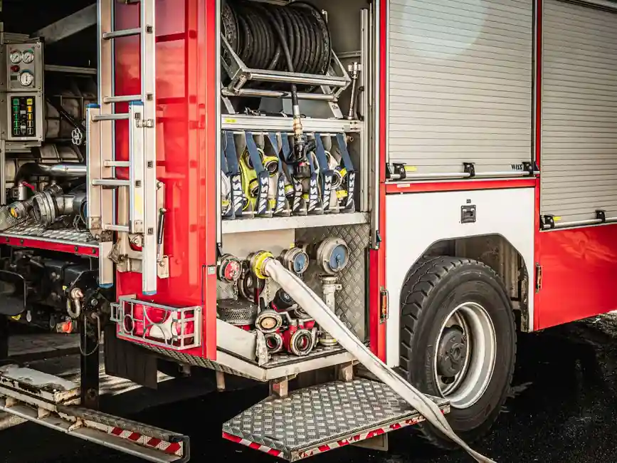
Safety relief valves protect pulp and paper equipment and personnel by limiting overpressure, with sizing, installation, testing, and maintenance treated as one selection system [S8].
The application spans steam, liquor, chemical recovery, bleaching, and water-treatment duties, where abrasives, corrosive chemicals, temperature changes, and deposits make the process medium and installed piping as important as the valve model [S1][S3].
Define the relief duty before choosing a valve
A safety relief valve must be matched to the protected system, relieving medium, fluid phase, design pressure, operating pressure, required capacity, and relief scenario; pressure relief valves are used to protect equipment and personnel by keeping fluid pressure within a safe range [S2][S8].
The maximum permitted accumulation and back pressure must be established for the connected equipment, while the valve inlet and outlet must be checked against the piping rather than selected from nominal size alone [S6][S8]. Parallel and staged relief arrangements may require separate hydraulic evaluation, including the possibility that one valve will not provide required capacity alone.
For pulp mills, document whether the relieved fluid is steam, condensate, black liquor, green liquor, bleaching chemicals, condensate, air, or water. A chemical stream can include sodium hydroxide, sodium sulfide, or chlorine dioxide, while pulp slurry can contain wood fibers, silica, and other abrasive solids [S3].
Compare conventional, modulating, and rupture-disc systems
Pressure relief valves are used to protect equipment and personnel from overpressure, while control valves are used to regulate fluid flow in pipes when precise flow control is required [S2].
The comparison should be based on four checks: certified capacity for the specified fluid and pressure conditions, compatibility with the relieved medium, installed back pressure, and access for inspection and testing. Insufficient capacity, excessive back pressure, or an unsuitable discharge system can negate an otherwise correct valve selection [S6][S8].
Account for pulp mill chemicals, steam, and deposits

Material selection must cover the normal process medium and the cleaning or boil-out chemicals used to remove scale and biological deposits, because a material compatible with one service may be attacked by the other [S1].
For bleaching and chemical recovery, verify trim, body, seat, gasket, and spring or bellows exposure against the specified chemistry. Sodium hydroxide, sodium sulfide, and chlorine dioxide can degrade materials that would appear adequate in a water service [S3]. For steam systems, compare valve metal and seating materials with the design temperature and pressure, not merely the operating temperature.
For liquor, pulp, and slurry systems, include solids content, fiber dimensions, and erosion characteristics in the review. Brown stock is moved through very large control valves, commonly 10–16 inches, demonstrating that fiber transport and abrasion are separate from pressure-relief sizing [S7]. A relief discharge should also be arranged so solids, pitch, or deposits cannot obstruct the valve or its outlet.
This preference must still be checked against the specified temperature, pressure, chemistry, and allowable seat leakage.
Fit the valve to piping, back pressure, and discharge
A correctly sized valve can still fail to relieve adequately when inlet pressure loss, discharge back pressure, or an undersized outlet removes effective capacity. The installation must be checked for the rated flow at the relief condition, not only at normal operating flow [S6][S8].
Steam service generally requires attention to outlet pressure and piping support because steam discharge can impose substantial reaction loads. The discharge route must also prevent condensate or liquid from collecting in the outlet, since accumulated liquid can create back pressure and impair operation [S8].
For corrosive or particulate services, consider a rupture disc upstream of the relief valve, but include the disc's pressure-drop and flow effects in the calculation. Locate the relief device so it sees the protected vessel pressure without intervening isolation valves, and provide means for inspection and testing. A full pressure-vacuum relief valve serves a different tank-venting duty and should not be substituted for an overpressure protection device.
Where a separate pressure/vacuum protection function is also required, evaluate it as a distinct safety-relief-valve application rather than assuming one device covers both positive-pressure relief and vacuum protection.
Choose metal or resilient seating from the service condition
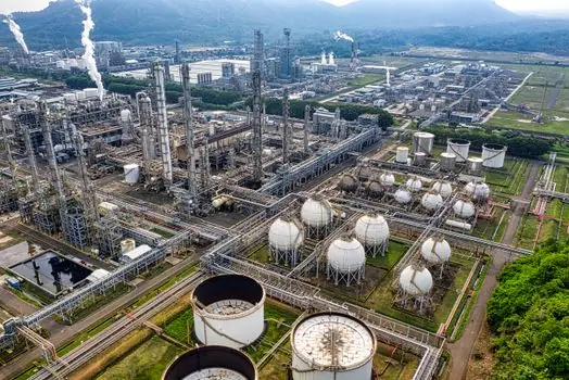
Use the pressure-temperature rating, allowable leakage, corrosion allowance, and materials of construction in the purchase specification. Confirm that the spring material, bonnet or body, guide, disc, seat, gasket, and bellows are suitable for the relieved medium and maximum relieving temperature. Clean steam and condensate service still require attention to condensate load and discharge piping.
Do not select a resilient seat solely because the installed medium is water. Chlorine dioxide, hot caustic, sulfide-containing liquor, and cleaning chemicals can attack elastomers. Conversely, do not select a metal seat without confirming that the required seating force and manufacturing configuration suit the valve size and set pressure [S1][S3].
Use built-in back-pressure compensation only when justified
A conventional valve exposed to discharge back pressure may require modification to maintain rated capacity and stable operation; balanced bellows designs are one established method of reducing the effect of back pressure [S6].
The decision depends on the difference between inlet pressure during relief and built-up discharge pressure. A balanced design may be attractive where discharge piping cannot be changed or where variable back pressure is credible. It is not a substitute for correct piping, because excessive back pressure or velocity effects can still impair capacity and operation.
For tanks that need both positive-pressure relief and vacuum protection, keep the functions distinct. A dedicated pressure-vacuum relief valve can protect against vacuum collapse, but it does not replace a pressure safety relief valve sized for the vessel's maximum allowable pressure and credible emergency case.
Specify testing, documentation, and maintenance access
Proper sizing, manufacture, assembly, test, installation, and maintenance are all required to obtain effective overpressure protection, making vendor documentation part of the selection rather than an afterthought [S8].
Require the purchase data to identify the applicable pressure-temperature table, valve model, size, set pressure, capacity at the specified relieving conditions, allowable overpressure, seat leakage class, materials, and test method. The high-pressure, corrosive-service review must also address installation, maintenance, and testing [S6].
Maintain a field-test route that permits inspection and lift or reseat testing without extensive dismantling. For steam service, verify that condensate draining provisions prevent water hammer or damaging liquid accumulation. For corrosive services, confirm that personnel can safely inspect the valve, rupture disc, flange joints, and discharge path.
The sizing and selection basis should remain traceable through design review, purchase, installation, commissioning, and subsequent inspections. Changes to operating pressure, fluid composition, relief temperature, piping, or back pressure require the relief case to be revisited, not merely the set point adjusted.
Use the safety relief valve selection criteria for power generation as a secondary comparison only where the mill also has steam-generation duties, because steam-plant practices provide relevant discipline but do not replace pulp-and-paper material and fouling assessments.
Match the final choice to service and failure consequences
The correct safety relief valve is the one with verified capacity, acceptable installed back pressure, compatible materials, suitable seating, a safe discharge route, and test access for the specific pulp-and-paper service. [S2]
For steam, condensate, and relatively clean services, a conventional valve with metal seating is generally the practical baseline. Consider modulating control or rupture-disc isolation where the process chemistry, fouling tendency, or pressure-control requirement justifies added complexity.
Do not use an ordinary isolation or control valve as overpressure protection, and do not accept a relief valve selected solely by inlet size or nominal pressure. Before purchase, close three documents: the credible relief cases with calculated capacity, the material and fouling assessment, and the installed piping and back-pressure review. This shortlist logic prevents an equipment-limit decision from becoming an installation or operating-limit failure.