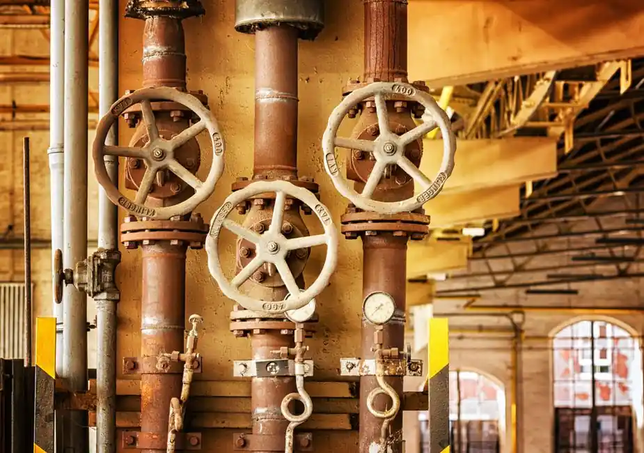
Mechanical seal replacement on a centrifugal pump follows a defined seven-step sequence, beginning with power isolation and ending with a controlled leak test, per standard seal-installation practice [S1][S2].
Across pumps, mixers, and agitators, the failure pattern is the same: contamination on the lapped faces, dry running, or shaft geometry outside tolerance. The installation procedure is built to eliminate each of those root causes before the equipment is energised [S3][S4].
Pre-Installation: Lockout, Drain, and Geometry Checks
Lockout/tagout of the driver and verification that the main breaker is open is the first mandatory step, because a back-spinning centrifugal pump can drive the impeller and rotate the shaft during seal work [S2]. Both inlet and outlet isolation valves must then be closed and the casing drain plug removed so the seal chamber is at atmospheric pressure before any cover is lifted [S2].
Before a new seal is unpacked, the shaft and seal chamber must be measured against the cartridge seal acceptance table: shaft runout at the seal area not to exceed 0.003 in (0.08 mm), axial end play not to exceed 0.005 in (0.125 mm), and stuffing-box-to-shaft concentricity within 0.002 in (0.05 mm) [S4]. Bearings must be checked for wear and axial/radial play, because worn bearings create the vibration that separates the seal faces and produces post-startup leakage [S4].
Disassembly of the Old Seal
On a back-pull-out centrifugal pump, the spacer element in the coupling is removed, the casing bolts are un-torqued, and the bearing-frame assembly slides away from the casing so the seal can be reached without breaking the process piping [S2]. Close-coupled designs require the entire pump-and-motor assembly to be removed because the motor shaft is the pump shaft [S2].
The impeller must come off before the seal, since the seal sits directly behind it on the shaft. Screwed impellers are removed by holding the shaft with a wrench and rotating the impeller clockwise; bolted impellers are removed by extracting the retaining bolt while the shaft is locked [S2]. With the impeller clear, the rotary seal part is slid off after the set screws are loosened, and the stationary face is pressed out of the seal-chamber bore [S1][S2].
Defining Working Height Before Mounting
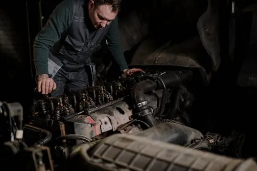
The first mechanical step in mounting a mechanical seal is to define the working height, the axial position of the seal faces relative to the shaft end, before the static face is inserted into the housing [S3]. This dimension is set by the seal manufacturer and is non-negotiable, because it controls the face load and the compression of the secondary O-rings.
The static (stationary) face is then inserted into the housing or gland, and the rotary face is slid onto the shaft in the correct orientation. A thin film of fluid-compatible lubricant is applied to the shaft or sleeve to let the seal glide on without scoring the secondary seal [S1]. The sealing faces themselves must not be touched, and the assembly must not be dropped, because any chip on the lapped face will become a leak path within minutes of startup [S1][S3].
Cartridge vs Component Seals: Installation Differences
A cartridge mechanical seal is supplied as a pre-assembled unit with setting clips that hold the faces apart during shipping and installation; the installer slides the cartridge onto the shaft, tightens the gland bolts evenly in a cross pattern, secures the set screws, and only then removes the setting clips before startup [S4]. Component seals require the installer to set the working height, fit the stationary face, then the rotary face, and adjust the springs or bellows by hand, with no factory pre-set gap to lean on [S1][S3].
Decision criteria for the two designs line up as: installation time (cartridge is roughly half the labour of component seals on a back-pull-out pump), field serviceability (component seals can be re-set in-situ, cartridge seals are usually replaced as a unit), tolerance for misaligned stuffing boxes (cartridge absorbs more axial movement), and skill required (component seals need a technician who can read a seal drawing and measure working height) [S1][S3][S4].
Reassembly, Torque, and Leak Test
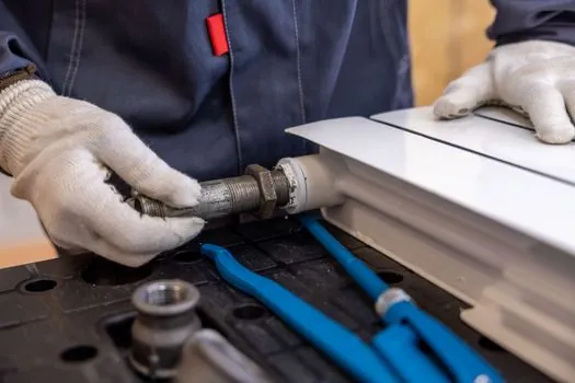
Reassembly proceeds in reverse of disassembly: impeller, casing, and bearing frame go back with all fasteners torqued to the equipment manufacturer's value, not by feel, because uneven gland loading is a documented cause of post-installation leakage [S1][S4]. A torque wrench is the only acceptable tool for the gland bolts on a cartridge seal; a rubber mallet is used to seat parts that need a gentle axial nudge, never to drive the seal onto the shaft [S1].
Before the motor is energised, a static leak test is performed at low pressure to confirm gasket integrity, followed by a brief operational test at reduced speed to verify face lubrication and thermal behaviour [S1]. For agitator and mixer seals, the fluid being sealed, not just the housing pressure, defines material selection: chemical compatibility, balanced versus unbalanced pressure class, and continuous operating temperature must all be confirmed against the seal datasheet before the seal is mounted [S3].
Failure Modes, Dry Running, and When to Replace, Not Repair
The most common post-installation failure on a cartridge seal is leakage traced back to setting clips that were not removed before startup, which mechanically hold the faces apart and produce immediate external leakage [S4]. The second is dry running: a mechanical seal requires a fluid film between the lapped faces, and starting the pump before the casing is flooded will score both faces within seconds and is not recoverable by re-torquing [S3][S4].
Replace, do not repair, when the shaft runout exceeds 0.003 in (0.08 mm), when bearing radial play is detectable by hand, when the stuffing-box face has burrs or corrosion that a gasket cannot compensate for, or when the seal faces show visible heat tinting, frosting, or chipping on inspection [S4]. For pumps handling flammable or toxic service, a double mechanical seal with an internal set in product and an external set as a safety barrier is the configuration of record for explosive-atmosphere service, not a single seal with a throttle bush [S3].
Trackable signals for the next maintenance window: a baseline drip rate measured in drops per minute after the first hour of operation, and a face-temperature reading taken with an IR thermometer at the gland after one hour, both compared against the seal manufacturer's commissioning values before the unit is signed over to operations.
Detailed specification references: mechanical seal, linear guide, and crossed roller guide.
Related analysis: PCB Raw Material Sourcing Guide: CCL Cost Stack, Copper Weight, and Substrate Specs.