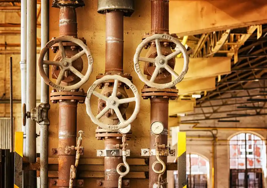
Medium-phase pneumatic conveying typically runs at line pressures up to 2 bar (about 30 psig) and particle velocities of 5 to 12 m/s, occupying the design space between dilute-phase suspension flow above 4,000 ft/min and dense-phase slug flow at 15 to 50 psig [S1][S8].
Capacity bands span roughly 1 to 50 t/h, distances of 100 to 400 m are common, and the operating envelope is set by avoiding both saltation (the lower bound) and excessive pipe wear (the upper bound) [S1][S8][S3]. The pneumatic conveying regime sits between the high-velocity, low-pressure dilute phase and the low-velocity, high-pressure dense phase, which is why the same engineer may spec three different blowers, three different pipe sizes, and three different solids-feed devices for the same powder.
Pressure Range and Why It Stops at About 2 Bar
Medium-phase line pressure is consistently quoted as 1 to 2 bar gauge (14.7 to 30 psig), with negative-pressure variants reaching about −500 mbar on the vacuum side [S8]. The upper bound is set by two practical limits: above roughly 2 bar, saltation velocity in horizontal runs rises and the system tends to flip into dense-phase slug behaviour, defeating the purpose of running medium phase in the first place [S1][S5].
For comparison, dilute-phase positive-pressure systems are typically specified below 1 bar (15 psig) at loadings up to 15 kg solid per kg of air, while dense-phase systems use 15 to 50 psig (about 1 to 3.4 bar) to push slugs at low velocity [S10][S7]. The minimum conveying velocity for a medium-phase line is around 3.5 m/s at 101.3 kPa local atmospheric pressure, which is the saltation floor that the blower must always exceed regardless of the static pressure setting [S5].
Air Velocity, Solids Loading, and Solids-to-Gas Ratio
Particle (not air) speed in medium phase sits between 5 and 12 m/s, with 8 m/s as a common design point for free-flowing granules and 6 m/s for friable powders [S8]. The solids-to-gas mass ratio (Ms/Mg) typically lands between 15 (the dilute-phase ceiling) and the dense-phase minimum that depends on material permeability, giving a usable solids loading of roughly 15 to 40 kg of product per kg of conveying air for free-flowing materials [S10][S1].
This is a materially narrower operating window than dilute phase, which is why medium phase is treated as a transition regime and is sometimes called strand phase or mixed phase. Stability hinges on controlling gas velocity right at the material pickup point: if velocity drops below saltation, the line plugs; if it climbs past about 15 m/s, the system is back in dilute-phase territory and pipe erosion rates rise sharply [S1][S5].
Distance, Capacity, and Where Medium Phase Fits the Sizing Matrix
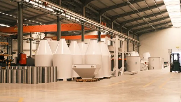
Medium-phase systems are typically specified for conveying distances of about 100 to 400 m, with single-stage pneumatic runs rarely exceeding 1.5 km in practice regardless of phase [S5]. Capacity sits between the dilute-phase ceiling of about 50 t/h at 10 to 15 psig and the dense-phase envelope of 200 t/h at 20 to 45 psig, giving medium phase a real-world range of 1 to 50 t/h at 15 to 30 psig [S2][S8].
The table below lines the three phases up against the four most common selection criteria; values are taken directly from the cited material, so a specifier can copy them straight into a datasheet enquiry:
Dilute phase: line pressure <1 bar (typically <15 psig), air velocity >4,000 ft/min (>20 m/s), solids-to-gas ratio up to 15:1, capacity to 50 t/h, distances short to moderate [S1][S10][S2].
Medium phase: line pressure 1 to 2 bar (14.7 to 30 psig), particle velocity 5 to 12 m/s, solids-to-gas ratio roughly 15 to 40:1 for free-flowing materials, capacity 1 to 50 t/h, distances 100 to 400 m [S8][S3][S10].
Dense phase: line pressure 15 to 50 psig (1 to 3.4 bar), particle velocity 1 to 5 m/s in slug flow, solids-to-gas ratio often above 40:1, capacity to 200 t/h, distances long and multiple discharge points [S2][S7][S9].
Materials It Is For, and Materials to Avoid
Medium phase is well matched to free-flowing granules and pellets with particle sizes up to about 2 inches at typical bulk density (16 to 3,200 kg/m³), non-abrasive or mildly abrasive powders, and applications where a moderate conveying distance rules out a simple vacuum system [S4][S3]. It is the default choice when the material cannot tolerate the high velocity of dilute phase but does not have the air retention or permeability required for stable dense-phase slug flow [S5].
It is not the right pick for highly abrasive materials (sand, glass batch, refractory batch), for which dense phase keeps particles away from the pipe wall, nor for moisture-sensitive or oxidisable powders where the user wants to switch to nitrogen as the carrier gas in a sealed dense-phase rig [S3]. Friable products that need the lowest possible particle-to-particle and particle-to-wall contact generally belong in dense phase as well, because medium-phase operation still runs at 5 to 12 m/s, which is well above the 1 to 5 m/s slug speeds used to protect such materials [S3][S8].
Blower Sizing, Filter-Receiver Sizing, and Common Failure Modes
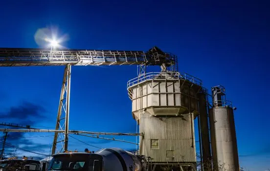
For positive-pressure medium-phase service, a lobe-type or screw-type blower is normally selected to deliver 1 to 2 bar gauge at the required mass flow; vacuum-side medium-phase runs use lobe blowers pulling 3 to 15 inches water column for short distances, or screw blowers pulling 16 to 26 inches mercury for long distances such as ship unloading [S2]. The filter-receiver downstream of the conveying line must be sized for the higher solids load of medium phase compared with dilute phase, and the rotary airlock or blow-through vessel feeding the line must be capable of metering at the target Ms/Mg without surging.
Three failure modes dominate medium-phase field service: (1) operating too close to the saltation point, which causes dune flow, unstable line pressure, and product drop-out; (2) running the line too hot, which pushes the system into dilute-phase erosion territory and accelerates bend wear; and (3) miscalibrating the pressure regulator, which lets the line pressure drift above 2 bar and collapses the system into dense-phase slugging that the downstream filter and airlock were not sized for [S1][S7]. The conveying limit always relates to a minimum velocity of about 3.5 m/s over the range of pressures considered, so any control loop that allows velocity to drop below that floor at full pipeline pressure is a plug waiting to happen [S5].
Standards, Measurement, and Where the Specifications Come From
Pressure and velocity figures here are drawn from OEM operating data and from continuing-education reference texts, not from a single international standard; pneumatic conveying sits outside the scope of IEC 60079-x and ATEX 2014/34/EU, which govern hazardous-area equipment selection rather than conveying hydraulics [S1][S2][S4]. Differential pressure across the conveying line is the primary process variable, and modern OEM transmitters can offer 32 selectable pressure ranges in Pa, mm water column, and inches water column to match the 1 to 2 bar operating window [S6].
Bulk density of the conveyed product, taken at 16 to 3,200 kg/m³ (1 to 200 lb/ft³), is the second key input; the same conveying rig will behave very differently across that range, which is why a single set of medium-phase numbers cannot be reused blindly across product grades [S4]. Designers also confirm the local atmospheric pressure (typically 101.3 kPa at sea level) when calculating the absolute conveying limit, because both the saltation velocity and the available pressure head above atmosphere shift with altitude [S5]. For more on the broader pneumatic conveying envelope, see the pneumatic conveyor and pneumatic actuator reference pages, and for how medium-phase flow fits into a plant's overall material handling layout, the conveying overview is the natural starting point.
Trackable signals for the next 6 to 12 months: any new OEM curve data tying Ms/Mg to pressure drop at 1.5 bar specifically (the centre of the medium-phase window), and any field report of stable medium-phase operation above 2 bar with non-permeable powders, which would extend the conventional pressure ceiling cited here.
For related coverage, see Roller vs Ball Bearing Dynamic Load Rating: Same-Bore Comparison.