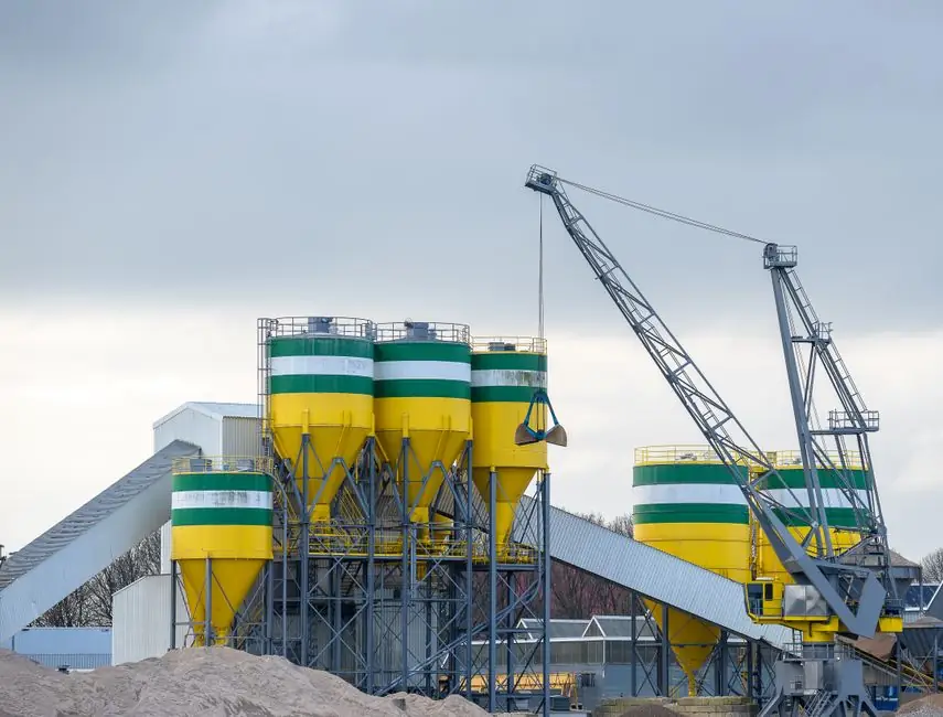
Medium-phase pneumatic conveying, also called strand phase or mixed phase, occupies the hydrodynamic window between dilute suspension flow and dense slug flow, with operating air velocity in the 600–2,500 ft/min band and solids loading ratio generally around 15–20 lb of solid per lb of conveying gas [S5][S10].
It exists because most real bulk materials do not behave neatly as either fully suspended fines or fluidisable coarse powders, and the middle regime is where most production transfer lines actually run once filter, blower, and pipeline economics are balanced [S1]. The classification is not a single number but a hydrodynamic envelope, and a system crossing into the medium band at any point in the line is, by most practitioner definitions, running medium phase.
Where the Three Phases Sit on the Phase Diagram
The standard reference plot of solids-to-gas mass ratio (Ms/Mg) against gas velocity shows three distinct operating regions: dilute homogeneous flow at high velocity and low Ms/Mg, dense plug or moving-bed flow at low velocity and high Ms/Mg, and a medium transition region in between where dune and unstable dune flow dominate [S1]. Dense phase systems cap out at roughly 2,500 ft/min and a loading ratio of 20–150 lb solid per lb gas, while dilute phase systems sit at 4,000–6,000 ft/min and no more than 15 lb solid per lb gas [S5].
One kilogram of standard air occupies about 800 L, the rough volume of four 200 L steel drums, which is why a dilute-phase line at 15 kg solid per kg air needs blowers, filters, and receivers sized for that order of magnitude of airflow per kilogram of product [S4]. For an industrial conveying system selection, the question is not which phase is best in the abstract but which envelope the material's saltation curve, pipeline length, and allowable pressure drop actually fall inside.
Air Velocity Ranges by Material and Phase
Conveying air velocity in dilute phase typically spans 18–35 m/s for a wide range of powders and granules, with the lower end of about 10–12 m/s reserved for fine powders and the upper end above 16 m/s for fine granular material, climbing further for larger or denser particles [S3][S6]. Fine cement and similar fine powders need a minimum pickup velocity in the 2,000–2,200 ft/min range, with general fine powders at 2,000–2,400 ft/min, and coarser materials requiring higher [S7].
In dense phase, the gas stream slows to 600–1,000 ft/min for plug flow and 800–2,500 ft/min for dune flow, while the solids themselves creep along at 20–200 ft/min in plug and 40–400 ft/min in dune regimes [S5]. A dense-phase line operating at a solids loading ratio of about 140 can hold minimum conveying air velocity down near 600 ft/min, which is the floor of what most engineers will accept before the line risks full plug stall [S8]. Practitioners building a pneumatic conveying line for a new bulk-solid product should start with the saltation velocity and then choose the operating point 10–20% above it for dilute or 10–20% below it for dense.
Solids Loading Ratio: The Defining Knob

Solids loading ratio, defined as the mass of solids conveyed per unit mass of conveying gas, is the single most useful classifier between phases, and the cut points are sharper than most marketing literature suggests [S1][S9]. Dilute phase is bounded by ratios well below 15, medium phase lives in roughly 15–20, and dense phase extends from 20 up to 150 in standard dense-phase designs [S4][S5].
The practical engineering range for medium phase is therefore narrow, and a line drifting up or down by even a few units of ratio will change flow pattern, pressure gradient, and pipeline wear behaviour in measurable ways [S10]. Operating closer to the lower edge of the dense-phase window (ratio 20–30) often gives the best compromise for abrasive materials, since solids velocity is low but the line is not yet fully plug-bound, a trade-off that shows up frequently in the construction machinery and equipment supply chain for cement, fly ash, and ground-granulated blast-furnace slag transfer.
Comparison of the Three Phases on Decision Criteria
The choice between dilute, medium, and dense phase is dominated by four criteria: conveying air velocity, solids loading ratio, specific energy per tonne, and allowable pressure drop. Dilute phase runs at 4,000–6,000 ft/min (about 20–30 m/s) with ratio below 15, the highest specific energy cost, and pressure drop below 1 bar, which suits long distances and multi-receiver layouts but punishes the filter and blower package [S2][S4].
Medium phase runs at 3,000–5,000 ft/min gas velocity and 2,000–4,000 ft/min solids velocity, with ratios straddling 15–20, intermediate specific energy, and pressure drops that depend on line length and solids properties [S5]. Dense phase operates at 600–2,500 ft/min with ratios of 20–150, the lowest air demand per tonne, and pressure drops that can exceed 1 bar, so the line is short and the receiver vessels are rated accordingly [S5][S2]. Engineers specifying for a new line should pin these four numbers before talking to vendors: the wrong combination is the single most common root cause of unstable flow, saltation, and pipeline wear.
Failure Modes and Instability in the Medium Window
Medium phase is operationally the riskiest band because it sits on the unstable slope of the carrying-capacity curve, the saltation point that marks the maximum in solids flow rate for a given gas flow rate [S1]. A small drop in gas velocity at the pickup point will drop particles out of suspension; a small rise will push the line into fully suspended dilute flow and increase wear on bends and elbows.
Dune flow and slug flow are both observable in this band, and at the saltation maximum the flow hydrodynamics are by definition unstable, so commercial systems are designed to operate slightly above the saltation velocity for dilute or clearly below it for dense, never at the peak [S1]. Dilute-phase strand flow at 3,000–5,000 ft/min gas velocity and 2,000–4,000 ft/min solids velocity is the visible warning sign that a line has slid into the medium-phase envelope, and corrective action is usually to re-tune the blower, re-size the feed venturi, or both [S5].
Sizing the Line: Calculation Anchors and Standard References
The minimum gas velocity required to keep particles suspended is the first calculation anchor, and typical ranges for this anchor sit at 3,000+ ft/min depending on particle density, with denser and coarser materials pushing the figure higher [S10]. Solids load ratio is then computed from the design solids mass flow divided by the design air mass flow, and the two together define the operating point on the phase map.
Most published correlations, including those in the Handbook of Pneumatic Conveying Engineering, are anchored to the saltation curve and the Ms/Mg ratio, and they apply across positive-pressure, vacuum, and combined push-pull layouts [S8]. For abrasive or friable products, the secondary criterion is peak particle velocity, which scales with the square root of the gas density and the slip velocity; this is the figure that controls bend erosion and product degradation, not the line-average velocity printed on the blower nameplate. For an industrial buyer, the verifiable next step is to obtain the manufacturer's saltation curve for the specific bulk solid at the design moisture content, then size the blower 10–20% above the dilute-phase minimum or 10–20% below the dense-phase maximum, depending on the chosen phase.
Detailed specification references: medium voltage vfd.
For related coverage, see ISO 22915 tilt-table stability test for forklifts: scope, parts, and lab workflow.