
Modbus TCP keeps the same four-quadrant register model defined by Modicon in 1979, layering it on top of TCP port 502: coils (1-bit, read/write), discrete inputs (1-bit, read-only), input registers (16-bit, read-only) and holding registers (16-bit, read/write) [S1][S4].
Each register type is accessed by its own function code, and the data sheet offset the integrator reads in a vendor PDF is almost never the byte the master has to put on the wire, a one-off difference that trips up roughly every first-time deployment [S3][S7].
The four Modbus register types and what each one holds
Coils are 1-bit, read/write storage, almost always used for digital outputs such as relay or contactor commands, and are addressed by function code 1 (Read Coils), 5 (Write Single Coil) and 15 (Write Multiple Coils) [S1][S7]. Discrete inputs are the 1-bit, read-only mirror of coils, typically wired to digital input modules and read with function code 2; the Modbus Organization describes them living in the absolute address band 10001 to 19999 [S4].
Input registers are 16-bit, read-only words, used for measured values such as analog inputs or counter snapshots, accessed with function code 4 [S1][S6]. Holding registers are 16-bit, read/write words and are the most universal type, accessed with function codes 3 (read), 6 (write single) and 16 (write multiple); they cover setpoints, configuration, and any parameter the integrator must change at runtime [S1][S7].
For anything wider than 16 bits, the protocol still ships the value as two adjacent 16-bit registers, which means a 32-bit float or a 32-bit integer is not a single object on the wire, it is a register pair whose byte and word order must be agreed between master and slave [S1]. Prosoft's Modbus TCP primer explicitly states that all I/O values are accessed via 16-bit input or holding registers per the device register map, with input registers containing read-only information [S6].
Address convention: 1-based tables, 0-based protocol offsets
The single most common commissioning error is sending the table offset from the vendor datasheet straight into the master's address field, because Modbus PDU addresses are 0-based while almost every printed register map is 1-based [S3]. The conversion rule is: protocol address = printed register number minus 1, applied separately to each of the four register spaces [S3][S7].
Automation Forum's July 2026 reference restates the four Modbus register types and emphasizes that coils and discrete inputs are bit-oriented, while input and holding registers are 16-bit words, and that any cross-type address reuse is invalid because each type lives in its own logical memory space [S7]. A practical check: holding register 40001 on a datasheet is PDU address 0x0000 sent with function code 3; input register 30001 is PDU address 0x0000 sent with function code 4; coil 00001 is PDU address 0x0000 sent with function code 1; the leading digit (1, 3, 4) is a human convention, not a wire field [S3][S4].
For a multi-channel digital slice, the bit count matters as much as the offset: function code 1 returns up to 2000 coils per transaction, function code 3 up to 125 holding registers, and function code 15 (Write Multiple Coils) can pack a whole 16-channel output module into one transaction, which the WAGO support thread confirms is the correct way to address 750-530 plus three 750-515 modules as a single 20-bit block at offset 512 [S2].
Wiring up a remote I/O coupler: one function code per register type
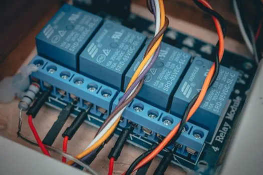
On a WAGO 750-series coupler behind an Ethernet fieldbus master, each I/O module occupies a contiguous bit or word range and must be accessed through the function code that matches its register type, not through holding registers as a generic fallback [S2]. A practical mapping for a 16-channel digital input slice 750-1405 is Read Discrete Inputs (FC2) starting at the module's bit offset, and a 2-channel analog input 750-474 is Read Holding Registers (FC3) starting at offset 0, because analog channels are 16-bit words even though the source is an input [S2].
The same 750-1405 plus 750-430 stack worked correctly when both were read as one 24-bit block under FC1, instead of two separate FC1 transactions, and the same logic let four 750-515 digital output modules be written as one 20-bit block under FC15 at a bit-based offset of 512 (0x0200) [S2]. This is the bit-vs-word trap the WAGO integrator hit: writing individual 4-channel modules with separate FC15 transactions at offsets 1, 2 and 3 produced no PLC state change even though the LEDs confirmed physical input, because the offset must be expressed in bits for coil function codes, not in modules [S2].
The article on taper-lock bushing wedge clamping shows a similarly strict "use the right protocol primitive" lesson: skipping the protocol-matched primitive (bit vs word, byte vs block) silently breaks the connection without throwing a comms error, exactly the symptom the WAGO poster saw. When in doubt, batch adjacent channels of the same type into a single FC1/FC2/FC15 transaction aligned to the start of the coupler, then add a separate transaction for the next register type [S2].
Slave address, unit ID, and the Modbus TCP default of 0xFF
Modbus TCP carries a unit identifier inside the MBAP header, even though TCP already resolves the endpoint, because the field preserves the original Modbus addressing model for bridges to serial subnets [S4]. The Modbus Messaging Implementation Guide recommends using 0xFF or 0x00 as a "non-significant" value for direct Modbus TCP communication, and most masters default to 0xFF, while some tools default to 0x00 and a few default to 1 (the historical broadcast-free slave address) [S5].
That mismatch shows up as ExceptionCode 0x02 (IllegalDataAddress) on perfectly valid addresses, because some slaves reject anything sent to the broadcast/zero unit ID while others ignore the field entirely [S5]. An Ignition-to-PLC thread on holding registers ended with the operator pinning the unit ID to match the working modpoll session, then resolving the residual 0x02 with a byte-order swap on the float register pair, not a re-wire of the register map [S5].
Prosoft's Modbus TCP introduction notes that input registers are read-only and holding registers cover configuration, which is the same rule that decides where to put a writable setpoint versus a read-only measurement in any custom register map you design from scratch [S6].
Comparison: register type vs function code vs payload size vs access

When you build or audit a Modbus TCP register map, the four data types line up against the function codes and the per-transaction payload ceilings as follows: coils use FC1/FC5/FC15, 1-bit payload, up to 2000 bits per FC1 read and up to 1968 bits per FC15 write, read/write; discrete inputs use FC2, 1-bit payload, up to 2000 bits per read, read-only; input registers use FC4, 16-bit payload, up to 125 registers per read, read-only; holding registers use FC3/FC6/FC16, 16-bit payload, up to 125 registers per FC3 read and up to 123 registers per FC16 write, read/write [S1][S7].
The selection rule for a given signal is straightforward: digital outputs go to coils so the master can pulse or latch them with FC5 or FC15; digital inputs go to discrete inputs so the slave hardware can update them asynchronously; analog measurements go to input registers so the master cannot accidentally overwrite a live reading; setpoints, calibration, and configuration go to holding registers so FC6 and FC16 can write them [S1][S4][S6].
Float32 and Int32 values are not first-class types in the protocol and must be carried as two adjacent holding registers or input registers, with the master and slave agreeing on byte order (big-endian, little-endian, or word-swapped) and the slave's datasheet listing the low-word-first vs high-word-first convention [S1].
Failure modes that look like wiring faults but are map errors
An ExceptionCode 0x02 response almost always means the master asked for an address the slave does not implement, and the first thing to check is the 1-based vs 0-based offset, not the cabling [S5]. An ExceptionCode 0x03 (IllegalDataValue) usually means the requested quantity overruns a register boundary, for example asking for 2 holding registers starting at address 0xFFFF, or asking for 16 coils on a 12-bit module; the WAGO case where 750-515 modules at offsets 1, 2 and 3 silently did nothing is a non-error variant of the same class of bug [S2][S5].
Bit-vs-word confusion produces the most misleading symptom: a value that updates once and then sticks, because the master is writing to the wrong function code space and reading from the right one, so the LED confirms the field wiring but the PLC tag never changes [S2]. The remote I/O module reference notes that the coupler is just a Modbus TCP slave with a fixed register map, and treating it like a generic tag database guarantees address-range errors on anything beyond the first module. A working counter-check on a fresh map is to use a third-party master (modpoll, Modbus Poll, QModMaster) to read each address the datasheet lists; if modpoll works and the SCADA cannot, the difference is almost always unit ID, byte order, or a stray 1-based offset in the SCADA tag [S5][S8].
Building a register map that survives the next commissioning

A defensible Modbus TCP map keeps coils and discrete inputs in the low offsets, then holding registers, then input registers, with each block aligned to a 16-bit boundary and a gap of at least one address between blocks so future expansions do not collide [S1][S3]. Floating-point setpoints should be documented as register-pair entries with the word order called out (e.g. "low word at address N, high word at address N+1, little-endian byte order"), and the datasheet revision date printed on the same page so the next engineer does not have to guess which version is loaded [S1].
For a 16-channel digital input slice plus an 8-channel digital input slice plus a 2-channel analog input plus four 4-channel digital output modules on one coupler, the published-working map from the WAGO thread is FC2 at offset 0 length 24 (24 discrete inputs), FC3 at offset 0 length 2 (one analog input, 2 registers), and FC15 at offset 512 length 20 (20 digital outputs, 1 bit each) [S2]. That mapping is the proof of the underlying rule: bit offsets for coil/digital function codes, word offsets for register function codes, and one transaction per register type, not one transaction per module [S2][S7].
The trailing signal to watch on the vendor side is whether new couplers keep the 750-style "coils at 0, registers at 0" dual-base offset model, because the moment a vendor ships a coupler whose coils start at a non-zero address, every SCADA tag built on the old default will throw IllegalDataAddress on the first poll cycle after the firmware update.
Spec-level background on the components involved: holding furnace, and o ring.