
A correctly sized motion controller is defined by four interacting parameters: the number of coordinated axes, the servo loop architecture (open-loop stepper, closed-loop position, or full torque-mode), the bus or pulse-train interface to the drive, and the feedback resolution required at the load [S1][S2].
Industrial motion controllers span 1-axis standalone units like the SMC100, 3-axis units such as the ESP302, and multi-axis modular controllers like the XPS family, each intended for a different stage class and coordination depth [S2]. CNC-class controllers such as the GRBL 0.9j-derived industrial board in [S3] address up to 8 axes with 32 discrete outputs and mechanical-button I/O for retrofit machining cells, with documented deployments across laser cutting, milling, plasma, and 3D printing.
Step Count 1: Quantify Axes, Coordination, and Loop Type
Begin with the mechanical bill of materials, not the catalog. Count every motor that must move, identify which pairs must be coordinated (gantry X-Y, rotary-theta with linear Z, electronic cam on a flying cutoff), and decide whether each axis is open-loop stepper, closed-loop position, or torque-mode servo [S2][S3]. A standalone 1-axis controller like the SMC100 suits a single linear stage with point-to-point moves, while a 3-axis ESP302 covers XYZ raster scans where path accuracy matters more than synchronization between many axes [S2].
Loop choice drives hardware cost more than any other decision. Open-loop steppers (controlled by the GRBL-derived architecture in [S3]) are acceptable where lost-step detection is non-critical and torque demand stays below roughly 50% of motor rating. Closed-loop position control with an external encoder is the default for stages carrying variable loads or operating near resonance. For high-dynamic applications, torque-mode control over a high-speed bus is required, but it pushes the controller into a tier with stricter loop-cycle requirements (commonly 1–4 kHz current loop) that not every multi-axis chassis can sustain [S2].
Step Count 2: Match the Drive Interface and Feedback Resolution
The controller-to-drive interface sets a hard ceiling on what the system can do. Three families dominate 2026 industrial practice: pulse-and-direction (step/dir) for low-cost stepper retrofits, analog ±10 V reference with encoder feedback for legacy servo stages, and digital buses (EtherCAT, PROFINET, CANopen) for synchronized multi-axis systems [S2][S3]. Pulse-direction suits the GRBL-class 8-axis board in [S3], where the firmware exposes stepper pulse control, stepper idle delay, and invert step/direction signals as tunable parameters. EtherCAT-class systems scale to dozens of axes with sub-millisecond distributed clocks but require drives and motors from the controller vendor's qualified list.
Feedback resolution must be specified at the load, not the motor. A 23-bit (approximately 8.4 million counts per turn) rotary encoder on a ball-screw stage with 5 mm lead yields roughly 1.7 nm theoretical resolution, far below the practical positioning repeatability of the stage itself, so over-spec'd encoders add cost without benefit. Specify encoder counts to deliver 5–10× the required positioning repeatability, and budget for backlash compensation in the controller's command path. Wave-spring preloading of the leadscrew nut, a common mechanical design choice, is governed by load, work height, and percent stress limits, and the same mechanical-discipline mindset applies to electronic tuning: keep percent stress at working height below 100% for static operation and below 80% for dynamic operation, with allowable wire-wall ratios between 3× and 10× the wire thickness [S1].
Step Count 3: Bus, Protocol, and Integration Footprint
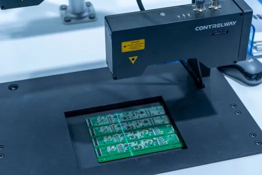
Protocol selection interacts with PLC and SCADA architecture. A standalone motion controller running on a vendor-proprietary bus is fine for a single instrument, but a plant-wide deployment typically needs EtherCAT, PROFINET, or Ethernet/IP so the controller can be programmed from the same IEC 61131-3 toolchain as the rest of the line. The XPS multi-axis controller family in [S2] exposes standardized fieldbus and TCP/IP interfaces specifically to sit inside a multi-vendor automation cell, and the GRBL-derived controller in [S3] ships with a browser-based UI and REST-style network access, which simplifies remote status monitoring without vendor-locked clients.
Digital I/O counts and software features deserve the same scrutiny. The industrial board in [S3] advertises 32 outputs, 6 programmable macros, soft limits, hard limits, homing feed-rate control, and homing pull-off distance, all of which are baseline items buyers should demand. A controller without configurable homing, soft limits, and a programmable fault response is a fit only for non-production or hobby-class machines, regardless of brand reputation. Vendors that publish their G-code interpreter limits, maximum feed rate, and idle-delay behavior in the same document are typically the ones whose firmware has been field-tested in production cells.
Step Count 4: Environment, Safety, and Mechanical Side-Constraints
Ratings matter as much as specs. Food, pharma, and outdoor installations need IP65+ enclosures, stainless hardware, and conformal-coated PCBs, while cleanroom semiconductor tools require low-outgassing materials and vibration-isolated chassis. For washdown or pharmaceutical lines, see the spec map in pharmaceutical motion controller sourcing, which covers motor, axis, and washdown combinations for those duty cycles. [S3]
Mechanical integration is where most sizing errors surface. A linear guide or crossed-roller guide with a load capacity only marginally above the moving mass will demand higher servo gains to compensate, which in turn forces a faster current loop and a controller with more headroom than the catalog "same-size" alternative would need. Similarly, where the mechanical system uses a PID controller structure for the servo loop, the controller's loop-update period must be at least 5–10× faster than the dominant mechanical resonance, otherwise the PID will excite, not damp, the mode. Reserve at least 30% of the controller's axis capacity for future expansion, and verify that the chassis supports the add-on modules (additional axes, I/O, fieldbus gateways) without firmware re-validation.
Who Should NOT Use a Multi-Axis Modular Controller

A multi-axis controller like the XPS in [S2] is wrong for a single-axis pick-and-place or a low-duty OEM instrument, where the per-axis cost premium and the unused fieldbus capability raise the bill of materials without returning throughput. Likewise, a GRBL-derived 8-axis board [S3] is the wrong tool for a high-speed packaging line that needs deterministic EtherCAT and SIL-rated safety, since its G-code interpreter and browser-based UI do not deliver the cycle-time guarantees or safety-integrity level a Category 3/PL d stop circuit requires. Match the controller tier to the duty, not to a wish-list of future features.
Sourcing Standards and Trackable Signals
Spec sheets should explicitly cite the bus protocol revision, the loop-cycle rate, the encoder-count resolution, the I/O count, and the safety standard claimed (commonly ISO 13849-1 PL d/e or IEC 62061 SIL 2/3 for industrial controllers). Confirm that any safety-rated claim is third-party certified, not vendor self-declared, and that the firmware revision is documented with a change log. As a shortlist test, the controller must expose: configurable homing with pull-off, soft and hard limits with debounce, programmable macros, real-time status reporting, and a documented maximum feed rate and stepper idle delay [S3]. Two trackable signals for 2026 sourcing: vendors that publish EtherCAT conformance test certificates alongside product datasheets, and vendors that disclose their mean-time-between-failure (MTBF) figures under stated temperature and vibration profiles, are the ones whose multi-axis controllers will pass a plant-engineering review on the first pass.