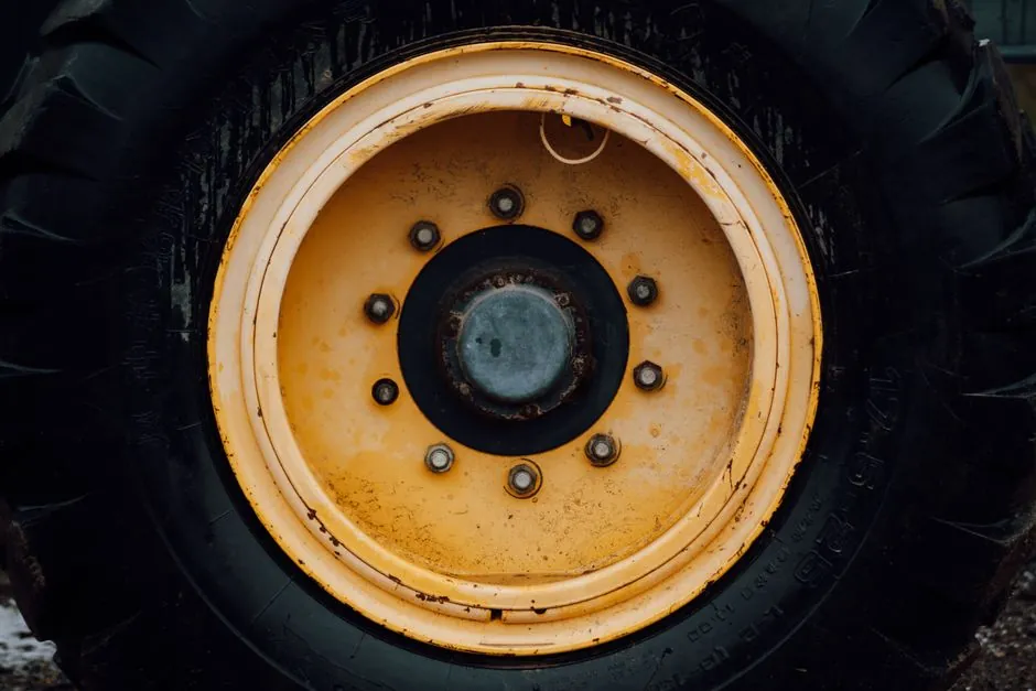
A motor grader levels surfaces by driving a long adjustable moldboard positioned between the front and rear axles, with engine power routed through a torque converter and powershift transmission to a closed-loop hydraulic system that repositions the blade in real time [S1][S3].
Cut quality depends on three coupled parameters: moldboard pitch (the angle between the cutting edge and the ground), moldboard tip angle (10-45 degrees for most work), and machine travel speed, normally held at 3-5 mph to prevent bounce and maintain a rolling cut [S2][S5].
Power Flow from Engine to Cutting Edge
Grader drivelines typically span 100-535 hp, with the largest mining-class units exceeding 161,000 lb machine mass and 24 ft moldboards [S4]. Power leaves the engine into a torque converter, then a powershift transmission with multiple forward and reverse gears, and finally a tandem rear-axle arrangement that splits torque across the two rear tires to keep tractive effort stable when the blade bites [S3].
The transmission feeds a dedicated hydraulic loop that drives the circle, drawbar, moldboard shift, lift, tilt, and articulation cylinders, so the operator can change blade position, slope, and side shift while the machine is rolling [S1]. Engine, hydraulics, and electronics are co-developed on current models so that the motor grader responds predictably across varying load conditions, including snow removal, ditch cutting, and fine road finishing [S4].
Moldboard Geometry: Pitch, Tip Angle, and Throat Clearance
Cut-and-rolling action is controlled by three independent adjustments. Moldboard pitch sets the angle the cutting edge makes with the ground; a 90-degree setting puts the edge vertical to the surface, which protects the edge and the retaining bolts from bending loads [S5]. Moldboard tip angle, the horizontal angle between the frame centerline and the blade, is normally held at 10-30 degrees in light free-flowing material and widened to 30-45 degrees when moving heavier cuts or working uphill [S2].
Moldboard throat clearance, the gap between the cutting edge and the upper moldboard face, is adjusted by tipping the moldboard forward. A wider throat lets material roll rather than bulldoze, which reduces required horsepower, cuts fuel burn, and lowers circle wear [S5]. A useful field rule: start the pass with the moldboard top roughly 2 inches ahead of the cutting edge, then trim from there based on soil type and moisture [S5].
Circle, Drawbar, and Articulation: How Six-Degree-of-Freedom Blade Control Works
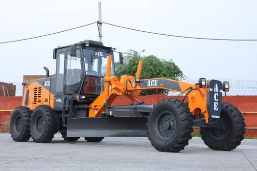
The moldboard rides on a ring gear called the circle, which sits inside a drawbar pinned to the mainframe. Two hydraulic motors rotate the circle to swing the blade left or right across the frame, while separate cylinders shift the drawbar side to side, lift and lower the entire assembly, and tilt the moldboard fore-aft and side-to-side [S3][S4].
Below the cab, an articulation joint lets the front frame angle up to roughly 20 degrees off the rear frame, so the front wheels can steer the machine into a curve while the rear follows [S4]. For washboard removal, articulating the rear frame 2-5 degrees toward the toe of the moldboard staggers the front tires; one tire crests a corrugation while the other drops into the valley, cancelling the bounce that would otherwise pump the blade [S5]. Crab steer, all four axles pointed the same way, is deliberately avoided during scarifying because it loads the shanks unevenly [S5].
Front Wheel Lean and Frame Geometry for Grading Accuracy
Front tires on most graders can be leaned inward or outward from the kingpins. Leaning the top of the tire toward the moldboard resists the lateral force the blade generates and keeps the front end from drifting off line, which is critical for finish passes on gravel and tight tolerance work around manholes and curbs [S4][S3].
For maximum stability during maintenance work, the main frame should be straight with the drawbar, and the circle should sit centered under the frame; any offset introduces side load on the front axle and reduces the effective width of each pass [S5]. Tire lean, articulation angle, and circle position are typically coordinated through grade control electronics on newer machines, which automate the adjustments the operator would otherwise make by joystick [S1][S4].
Operating Window: Speed, Material, and Failure Modes
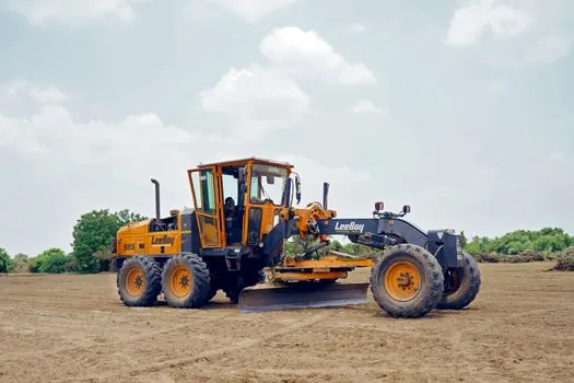
Most motor grader work is done at 3-5 mph, the band where the blade maintains a continuous rolling cut without bouncing [S2][S5]. At higher speeds the front axle starts to oscillate, the cut goes wavy, and cutting-edge impact loads rise sharply; at lower speeds material stacks ahead of the moldboard and the machine begins to bulldoze, which doubles the load on the circle and the drivetrain [S5].
Three common failure modes show up in the field. First, circle wear accelerates when material packs in the ring gear area and breaks the rolling action, so a stalled roll quickly becomes mechanical wear [S5]. Second, excessive down pressure on hard, dry surfaces chews cutting edges, raises fuel use, and drops productivity; the rule is to apply only enough force to keep material moving [S5]. Third, washboards reform fast if operators fill corrugations with loose dry material rather than cutting them to full depth and recompacting with moisture; a scarifier or serrated edge is the right tool for that cut [S5]. Routine wear parts, including cutting edges, scarifier shanks, and circle teeth, sit on a service schedule that fleet buyers should plan for alongside fuel and tires, much like the consumables covered in a bulldozer spares reference.
Comparison: Moldboard Adjustments and Their Effects
Operators tune the motor grader through six coupled adjustments, and each one trades productivity against wear. The table below summarises the practical envelope published in operator guidance [S2][S5].
Moldboard tip angle: 10-30 degrees for light free-flowing material; 30-45 degrees for heavy cuts and uphill work; steeper angles move more material per pass but require more tractive effort and raise side load on the front tires [S2]. Pitch (cutting edge to ground): 90 degrees is the default for stability and edge life; forward pitch widens throat and improves roll in cohesive soils; backward pitch concentrates the cut and is used for spot finishing [S5]. Throat clearance: start with moldboard top about 2 inches ahead of the cutting edge, then increase for sticky or wet material to keep the roll alive [S5]. Travel speed: 3-5 mph for grading; above this, bounce degrades cut quality; below it, material stacks and the machine bulldozes [S2].
Standards, Sourcing, and What Buyers Should Check
Operator training material is published by state Local Technical Assistance Programs, including the Michigan LTAP motor grader operator's manual, which is the most widely cited municipal reference for gravel road maintenance and dust control [S3]. Manufacturer operating guidance, such as Cat's motor grader operating tips, sets the practical envelope for tip angle and travel speed that fleets and rental contracts reference [S2].
For procurement, the engineering checks are straightforward: confirm engine power band against the cut profile (100 hp for municipal maintenance versus 500+ hp for mining haul road work), verify moldboard length matches the application (12-14 ft for road work, up to 24 ft for mining), and specify grade-control electronics if the project includes tight tolerance paving prep. Buyers building a spec-first purchasing workflow for adjacent wear items, such as filtration and driveline consumables, can use the same evaluation logic outlined for an industrial filter procurement workflow. Two trackable signals to watch: OEM integration of 3D mastless grade control on mid-frame graders, and broader use of electric drive hydraulics to cut idle fuel use on long shoulder-maintenance shifts [S4].
Component reference pages worth checking: ac motor, and drive motor.