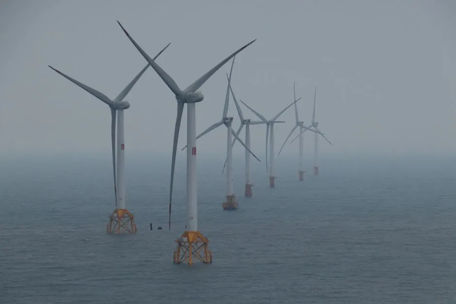
Offshore wind farms under construction in 2026 typically use 11–15 MW turbines on monopile foundations, with the SG 11.0-200 DD at South Fork Wind running at 200 m rotor diameter and 100.9–143.9 m hub height [S2]. Foundations absorb roughly 30% of project CAPEX, making the foundation fabrication line the single largest capex line item in any greenfield offshore wind build [S6].
Production line designers must synchronize three independent flows: tower-taper rolling cells, monopile and transition-piece welding stations, and nacelle/ drivetrain assembly. Each flow has its own bottleneck, and mismatched cycle times between them routinely delay installation campaigns by 6–12 months [S3][S5].
Capacity Anchors: 11–15 MW Turbines, 200 m Rotors, 30% Foundation Share
Front-end capacity sizing starts with the turbine: South Fork Wind operates 12 SG 11.0-200 DD units at 11 MW each, totaling 132 MW of installed capacity, with hub heights spanning 100.9–143.9 m and rotor diameter fixed at 200 m [S2]. Inter-array cabling on that site runs 34.5–66 kV while the export cable is a single 138 kV AC buried seafloor circuit with horizontal directional drill landfall [S2].
These are not academic figures: they define the line's maximum workpiece envelope, the largest single lift in the rolling cell, and the heaviest subassembly that the assembly hall floor load must accept. A line designed for sub-10 MW turbines cannot accommodate a 15 MW tower section without re-anchoring the rolling mill and re-grouting the assembly bay [S5].
Foundation Line: Monopile and Transition Piece Work Flow
Monopiles are the dominant offshore wind foundation type, and the GSP Madabhushi 2026 study reports foundations for offshore wind turbines form nearly 30% of total project cost, with monopiles the most popular form [S6]. A monopile production line typically runs plate preparation, longitudinal and circumferential SAW welding, ultrasonic and radiographic NDT, internal fit-out, and a final coat-and-cure station, with single-piece monopile masses in the 800–1,500 t range for water depths of 30–45 m [S2][S3].
Water depth drives the geometry: South Fork Wind sits in 33–41 m of water, 56.3 km from shore, and uses monopile support structures on a shallow-water soft-bottom site [S2]. Sites exceeding 60 m water depth shift the foundation mix toward jackets and floating substructures, which carry very different welding, bolting, and ballasting station requirements [S3]. Foundation design also feeds back into the rolling cell: tapered tower sections need CNC-controlled plate rolls capable of holding taper along the entire can length, a capability that Davi's custom automated lines explicitly market for the wind energy sector [S5].
Tower Line: Tapered Section Rolling and Can Welding
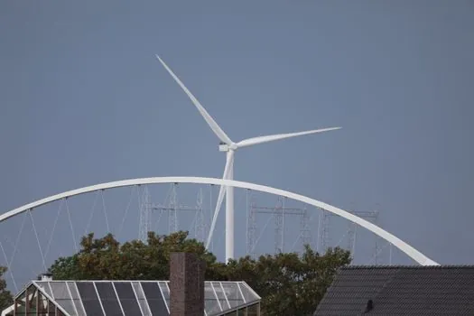
Tower production is the most automation-friendly of the three flows. Plate rolls with CNC taper control roll the conical frustums that make up each tower, then robotic seam welders join can-to-can joints before a flanged interface station mates the tower to the nacelle [S5]. A typical 11–15 MW tower is built from 3–5 tapered sections, each 20–35 m long, and the line cycle time is set by the heaviest single can, not the average [S3].
Designers should anchor the tower line cycle to a target of 2–3 complete towers per week for a 1 GW/year programme, with the rolling cell, the SAW welding cell, and the internal-fit-out cell each running at a matched takt. Imbalance at this stage shows up as a tower yard full of half-finished cans blocking the automatic molding line of tower sections into transport loads [S5].
Nacelle and Drivetrain Assembly: Stator, Rotor, Hub Mating
Nacelle assembly lines for offshore turbines are dominated by the main shaft, gearbox or direct-drive generator, and hub-mating stations, with the Siemens Gamesa SG 11.0-200 DD using a direct-drive generator that eliminates the gearbox but raises stator-handling loads [S2]. A direct-drive nacelle for an 11 MW unit weighs roughly 400–500 t fully assembled, and the assembly hall crane must be rated to the heaviest single lift, which is typically the bare stator or the rotor-plus-shaft subassembly [S3].
Layouts typically run a U-shaped flow with pre-assembly cells on the outer rails and a single final mating bay in the center, fed by a conveyor sorting line of gearbox, generator, and hub subassemblies. Test benches for pitch systems, yaw systems, and converter cabinets are positioned off the main flow as satellite stations with a 24–48 h soak-test buffer [S3].
Blade Line: Layup, Infusion, and Post-Cure Handling
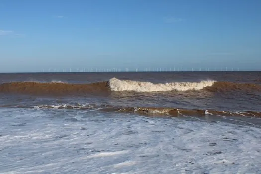
Blade moulding is the slowest of the three flows and the most site-dependent. A 100 m offshore blade requires a single-piece mould roughly 110 m long, an infusion hall with controlled temperature, and a post-cure trimming and coating station that handles blades weighing 35–55 t finished [S3]. Composite layup and resin infusion for an offshore-scale blade commonly run 24–48 h of cure time, and that cure window sets the line takt regardless of how fast the upstream stations run [S3].
Plants targeting 2–3 GW/year of blade output therefore need 6–10 active moulds in rotation, plus a separate finishing and paint hall, with a resin sand line or equivalent composite feed system delivering metered resin to the infusion manifolds on a controlled schedule. The bottleneck is cure time, not layup speed, and any production line that ignores the post-cure trim and coating window will pile up finished-but-uncoated blades in the yard [S3].
Logistics, Port Handling, and Installation Window Coupling
Production line output must match the offshore installation window, not just the in-house cycle time. South Fork Wind construction started in February 2022 and completed in March 2024, with operations from March 2024 and a planned decommissioning in March 2049, a roughly 25-year operating envelope that is typical of fixed-bottom offshore wind [S2]. The site uses one 138 kV export cable with horizontal directional drill landfall, fed by 34.5–66 kV inter-array cables, and that single export circuit is sized to carry the full 132 MW output [S2].
For higher-capacity builds, the transmission line itself becomes a project node. VicGrid is currently developing a new shared transmission line to connect Gippsland-coast offshore wind generation to the Victorian electricity grid, and the UK's interconnector programme links offshore wind clusters across the North Sea [S4][S7]. Production line planners should treat the export-cable drum yard and the load-out quay as integral stations of the production flow, with a line frequency furnace and rolling cell cadence that does not outrun the marshalling port's quay-side handling rate [S4][S7].
Comparison: Foundation vs Tower vs Blade vs Nacelle Flow on 4 Criteria
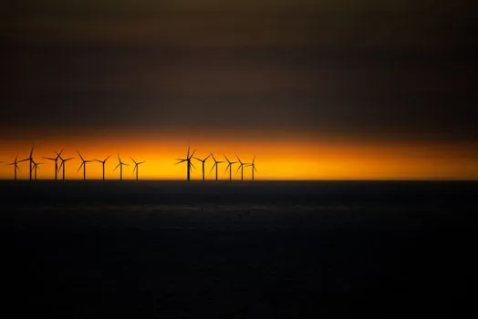
Engineers comparing where to spend capex on a greenfield offshore wind line should score each flow on cycle time, single-piece mass, automation depth, and port-handling sensitivity. The tower line scores best on automation and worst on port handling, since finished towers must be stored horizontally and consume large quay-side footprints. The foundation line scores worst on cycle time per t of steel but best on mass-handling maturity. The blade line scores worst on cycle time and best on direct value-add per square metre of plant. The nacelle line scores best on cycle time but worst on capex per station, given the clean-room and crane demands. [S3]
A useful rule of thumb: foundation capex dominates at roughly 30% of project CAPEX, turbine capex at roughly 40% including blades, and the remaining 30% covers cables, substations, and installation [S3][S6]. Inside the turbine's 40% share, the rolling cell for tower sections, the resin-infusion line for blades, and the nacelle assembly hall each take a roughly comparable cut, and a molding line decision for blades should be benchmarked against a rolling-cell decision for towers before either is committed [S3][S5][S6].
Risks, Failure Modes, and Sourcing Standards
The dominant failure mode in offshore wind production lines is schedule slippage caused by component-mix mismatch: rolling cells outrunning welding cells, welding cells outrunning NDT capacity, and finished-component yards outgrowing the marshalling port. South Fork Wind's 25-month construction window (February 2022 to March 2024) and 132 MW output are within the band that current European and US supply chains can sustain, but the next tier of 1+ GW projects with 15 MW turbines will test every station [S2].
Procurement risk is concentrated in a small number of suppliers: the South Fork Wind turbine developer is a single OEM, the foundation manufacturer is a single supplier group, and the export cable is a single 138 kV circuit with horizontal directional drill landfall [S2]. Engineering teams building a new production line should dual-source critical stations (rolling mills, SAW welding heads, NDT rigs, large stator handling cranes) and should require class-certification paperwork for every foundation, tower, and blade before it leaves the plant [S3].
Next signals worth tracking: DOE-funded floating offshore wind design and manufacturing research results from the IESO programme, the Gippsland shared transmission timeline, and the next wave of 15 MW nacelle assembly plant announcements in the US Northeast and the North Sea. Engineers planning capex now should freeze the foundation line first, since the rolling and welding cells have the longest lead time, then sequence the tower, nacelle, and blade lines to match the port and export-cable schedule. A related analysis of planetary reducer selection for wind power sits alongside the drivetrain cell, and a broader offshore wind manufacturing equipment sourcing map covers the rest of the bill of materials.