
Planetary reducers are the most common coaxial gearbox in wind power applications, with input and output shafts sharing a single axis to maximize torque density inside the nacelle envelope [S1]. For utility-scale turbines, multi-stage planetary units are specified for both the main rotor (low-speed shaft) and the yaw/pitch positioning drives, where compact length and high reduction ratio outweigh cost per kilowatt [S4].
Wind-specific duty differs from general industrial gearing: variable-speed rotor input, partial-load operation most of the year, grid-loss transients, and 20-year service intervals. That duty cycle is why the selection criteria below lean on torque rating, bearing support, and condition monitoring more than on ratio alone. Engineers comparing wind, mill, and textile drive options can cross-reference the planetary reducer spec map for steel mill drives, where similar torque-density logic applies to rougher ambient loads.
Why a Planetary, Not a Helical, in the Wind Drivetrain
Helical gear units use sequential meshing pairs across parallel-shaft stages, giving smooth operation and easy field service, but their length scales directly with reduction ratio [S2]. Planetary stages cut that length by sharing the load across multiple planet gears meshing simultaneously with the sun and ring, so a single stage can replace two or three helical stages at the same ratio [S1][S2]. In a 3-4 MW nacelle where every cubic decimeter of gearbox volume is fought over, that envelope advantage is decisive, and the trade-off is the precision required to assemble and maintain the planet carrier.
For non-coaxial paths inside the turbine, helical or bevel-helical units are still used in pitch and yaw gearbox sections where the input axis orientation is not fixed to the rotor axis. Within the same nacelle, designers commonly pair a planetary first stage with a helical second stage on the high-speed shaft to balance ratio, efficiency, and serviceability, a pattern also visible in the broader gearbox selection for textile mills spec maps where mixed trains dominate.
Key Spec Bands for Wind-Duty Planetary Reducers
Planetary units are specified by stage count, reduction ratio per stage, rated torque, backlash class, and bearing arrangement. Single planetary stages commonly run ratios from roughly 3:1 to 10:1, while two- and three-stage units for wind main gears stack into the 80:1 to 200:1 envelope, and dedicated yaw/pitch units are typically single-stage with low backlash for accurate blade-angle control [S2][S4].
Torque rating is the dominant selection variable on the main rotor path: a 3 MW class turbine main gearbox typically sees rated output torque in the order of 2.0-3.5 MN·m at the low-speed shaft, with peak transient torques 1.5-2.0× rated during grid loss events, so designers usually derate the planetary stages against those peaks rather than the steady mean. Backlash is split into arc-minute classes (commonly <1, <3, <5, <10 arcmin) and pitch/yaw duties almost always sit in the <3 arcmin band to keep blade-angle error inside the controller's deadband.
Bearing support is the spec item that quietly governs power density. Crimped planetary planet-carrier pins, such as Miba's EMPT design, are used to maximize torque per kilogram and shrink the planet-bearing envelope, a trend visible across 2026 wind-turbine gearbox platforms [S6]. Surface-treated pins, rolling-element planet bearings, and integrated oil scavenge paths now separate premium wind reducers from generic industrial units.
Selection Criteria: Matching the Reducer to the Turbine Subsystem
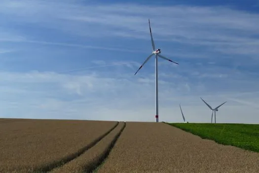
Selection criteria for a wind planetary reducer split cleanly across the three subsystems it serves. Main rotor (low-speed shaft) units need maximum torque density, two or three planetary stages, integrated torque-arm mounting, and oil-mist or forced-circulation lubrication sized for continuous duty. Yaw drive units are smaller, single-stage planetary reducers paired with multi-turn slewing bearings, where the spec focus is low backlash, holding torque without rotation, and IP65 sealing against tower-top weather ingress [S3][S4].
Pitch drive units are the third category, and they are the most safety-critical, since they must feather the blades in a grid-loss event. Here, planetary reducers with integrated overrunning clutches or electric back-up supplies are increasingly specified, with redundancy measured in seconds of actuation rather than hours of runtime. A useful side reference for the redundancy logic, particularly around holding-brake and energy-storage sizing, is the EPDM rubber selection for energy equipment map, where seal and elastomer choices gate the same continuous-duty envelope.
Reliability and Condition Monitoring: The 2026 Decision Driver
Wind-turbine gearboxes are the single largest O&M cost driver in the drivetrain, so 2026 selection logic puts condition monitoring on par with rated torque. Published cross-condition fault diagnosis work in 2026 confirms that planetary gearbox fault signatures remain hard to isolate under variable speed and load, which has pushed OEMs and owners to specify vibration, oil-debris, and acoustic-emission sensors at the factory rather than as retrofits [S7].
For spec-writing engineers, the practical translation is: require the gearbox supplier to deliver sensor tap-points on the planet-carrier housing, ring-gear bearing housings, and high-speed-shaft bearings, and to provide a documented interface (analog 4-20 mA, IEPE, or Ethernet-APL) compatible with the turbine SCADA. Buyers should also confirm oil-sample ports and that the bearing-supplier hardware (for example a crimped-pin planet carrier) is field-serviceable with standard pullers, since gearbox exchange on a tower-top crane is a 30-50 hour operation that dwarfs the cost of any single component.
Comparison: Planetary vs Helical vs Bevel-Helical for Wind Service
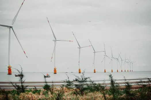
On torque density, planetary leads at 100-200 Nm per kg of gearbox mass in modern wind units, helical trails at 40-80 Nm/kg, and bevel-helical sits between, used mainly where a right-angle shaft turn is unavoidable [S2][S3]. On envelope length at the same ratio, planetary wins decisively because stages stack coaxially instead of along a parallel shaft, which is the single biggest reason nacelle designers choose it for the main rotor. On serviceability, helical is friendlier: it can be inspected stage by stage without disturbing the planet carrier, while planetary service usually means pulling the planet carrier as an assembly, which is why field crews prefer it for the main path only where the torque-density gain justifies the heavier lift [S2].
Limitations, Failure Modes, and Sourcing Risks
Planetary wind reducers fail most often at the planet bearings, planet pins, and ring-gear teeth, with white-etching cracks, micropitting, and macropitting the dominant surface modes under partial-load, variable-speed operation. Lubricant viscosity grade, oil cleanliness class (typically ISO 4406 18/16/13 or cleaner at the bearing feed), and water-content control now drive warranty terms more than steel grade alone, so the 2026 spec language should pin those three numbers explicitly. Sourcing risk is concentrated in forged ring gears, large-diameter planet bearings, and integrated torque-arm housings, where lead times of 30-50 weeks were still common in 2025-2026 deliveries. For non-wind reference points, the same long-lead forging constraint shows up in adjacent heavy-industry equipment, such as the diaphragm wall grab selection for urban infrastructure spec map, where gear-quality forgings gate the build schedule. [S3]
Track the AGMA 6006 and ISO 6336 calculation reports each supplier provides, the documented IEC 61400-4 design-load cases the unit was sized against, and the 2026 Miba or SKF bearing-support data sheets for the specific planet-pin and carrier geometry [S6]. If those three documents are not on the table during technical evaluation, the gearbox is not yet ready to specify, regardless of price.
Component reference pages worth checking: planetary reducer, power cable, and power distribution.