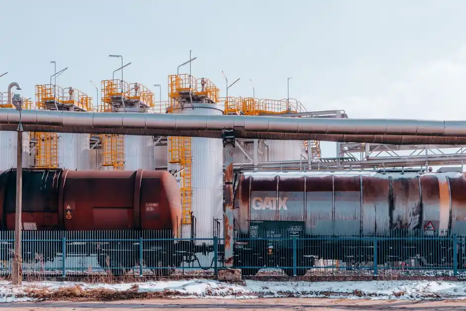
Oil and gas coating selection is not a single product decision: it is a zone-by-zone spec driven by the local service envelope, from -40°C cryogenic units to fired heaters running above 400°C, and by the failure history of the asset class [S4].
The reference framework most used in current specifications is ISO 12944 corrosivity categories (C3 medium, C4 high, C5 very high, plus CX and immersion ratings for continuous water contact) combined with application-side standards such as SSPC-SP 10 near-white blast cleaning for the pipe body and SSPC-SP 11 for field joint areas [S1][S5].
Buried Pipelines: FBE and Cathodic Protection as the Default
For buried gathering, transmission, and distribution lines, fusion-bonded epoxy (FBE) powder applied over SSPC-SP 10 near-white blast is the workhorse coating, applied shop-side by automation and field-jointed with three-layer shrink sleeves or 100% solids liquid epoxy [S1]. Cathodic protection is not optional: licensing a buried pipeline without it is effectively impossible, and the FBE coating and CP system are specified to work synergistically, with CP compensating for coating holidays as the FBE ages [S1]. For deeper context on how industrial coating systems are classified, the ISO 12944 corrosivity framework is the starting point. A practical decision contrast for buried vs. above-ground service looks like this:
Comparison criteria: Buried line (FBE + CP) typically runs 300–500 µm DFT, requires CP, and tolerates soil-resistivity variability; above-ground atmospheric systems run inorganic zinc primer + epoxy intermediate + polyurethane topcoat at roughly the same total DFT, but rely on the polyurethane topcoat for UV and color retention, not on CP [S1]. The buried-line choice trades cure time for long-term immersion performance, while the atmospheric system trades chemical immersion resistance for color and gloss stability.
Above-Ground Stations and Compressor Stations
At pump stations and compressor stations where pressure is reintroduced into the line, atmospheric exposure is the controlling factor: wind, rain, UV, and infrared drive the spec toward a three-coat system rather than an immersion-rated FBE [S1]. A typical shop-applied system is inorganic zinc primer plus an epoxy intermediate plus a polyurethane topcoat, with the same chemistry carried through to field joints to avoid galvanic or compatibility issues at the girth weld [S1]. CP is deliberately omitted on the above-ground sections because the line is no longer in a continuous electrolyte [S1].
Where a coating spec overlaps with construction-side assets, the same zone logic appears in industrial coating selection for construction projects, where C4–C5 atmospheric systems dominate the specification for refinery-adjacent pipe racks and structural steel.
Refinery and Petrochemical Zone Specification
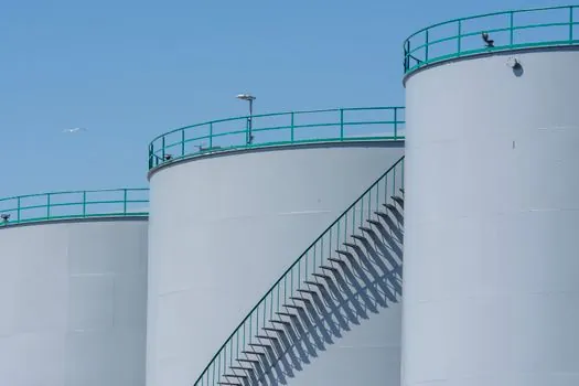
Inside the refinery fence, the coating spec becomes asset-specific and is rarely a single product. Refinery process equipment spans -40°C on cryogenic units to 400°C+ on fired heater and reformer tubes, with continuous H₂S and SO₂ exposure in many streams, intermittent hydrocarbon splash at flanges and sampling points, and a separate fireproofing requirement on load-bearing steel [S4]. For refinery structural steel the working envelope is ISO 12944 C4 to C5, with units near process equipment with hydrocarbon release potential pushed to C5 [S4].
A typical C5/high-durability system for refinery pipe racks and supports runs zinc-rich epoxy primer (80%+ zinc by dry weight) at 60–75 µm, a high-build or glass-flake epoxy intermediate at 2 × 125–150 µm, and a polyurethane or acrylic-polyurethane topcoat at 60–75 µm, for a total dry film thickness of 370–450 µm [S4]. Where fireproofing is also required (most load-bearing structural steel in process areas), the fireproofing sits on top of the anti-corrosion primer, and the primer must be qualified as compatible: cementitious fireproofing is commonly used for hydrocarbon fire resistance, with intumescent systems rated to UL 1709 applied on shop-fabricated modules [S4]. The line between coating and waterproof coating is the immersion boundary; for tank farms and offshore modules, that line is crossed frequently.
Subsea, Offshore, and Underwater Pipelines
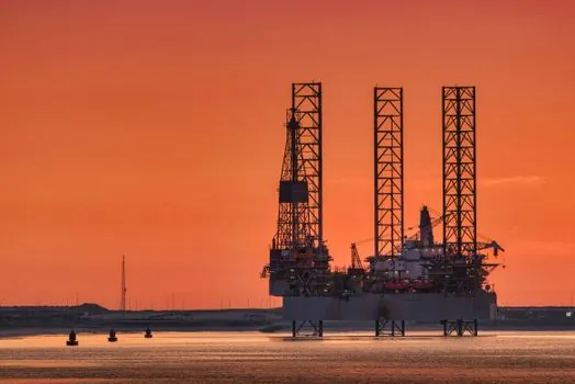
Underwater pipelines share an immersive environment with buried lines, so the coating logic converges even though the installation looks different. Pre-coated options are typically three-layer FBE systems; site-applied alternatives include coal-tar urethane, selected for field workability over shop-controlled FBE [S1]. For subsea Christmas trees, manifolds, and ancillary equipment, thermal spray coatings (HVOF, plasma, and flame spray) are widely specified for combined wear, high-temperature, and erosion resistance, complementing the corrosion-resistance stack on the parent metal [S3].
Offshore, where chloride-rich seawater, sand, and cyclic loading converge, the base materials typically shift toward super duplex stainless steel, Inconel 625/718, or titanium, with thermal spray or electroplated overlays used on bearing and sealing surfaces rather than as the primary corrosion barrier [S3]. On CNC-machined wetted parts such as valve bodies, valve stems, ball valves, and wellhead components, surface finishes below Ra 0.8 µm are common before any coating or plating is applied, because coating adhesion is roughness-controlled [S3].
OCTG and Downhole Considerations
For OCTG (Oil Country Tubular Goods), the coating decision is driven by the well chemistry, not by surface exposure. H₂S partial pressure, CO₂ content, chloride concentration, bottom-hole temperature, and bottom-hole pressure together determine whether a standard epoxy phenolic, a high-temperature novolac, or a thermal-spray overlay is specified, with NACE MR0175 / ISO 15156 sour-service limits forming the governing envelope in H₂S-bearing wells [S8]. For aggressive produced-water and high-temperature wells, internal coatings such as phenolic epoxy and baked phenolic linings are used to extend casing and tubing life; for sand-control or erosion-heavy service, thermal-spray tungsten carbide or chrome-carbide overlays are often applied to tool joints and crossover subs [S3][S8].
The seal stack at the wellhead and Christmas tree is a separate spec, and decisions on oil seal elastomers and back-up rings are made in parallel with the coating selection, because elastomer compatibility with H₂S, amines, and hot hydrocarbons is independent of the metal-side coating choice.
Selection Criteria: Five Questions That Drive the Spec
Five criteria consistently drive oil and gas coating selection in current vendor guidance: (1) environment corrosivity category per ISO 12944 (C3, C4, C5, CX, or immersion); (2) operating temperature range and peak temperature; (3) chemical exposure profile (H₂S, CO₂, SO₂, chlorides, hydrocarbons); (4) whether the asset is in immersion, splash, atmospheric, or fire-exposure service; and (5) inspection, surface-prep, and application access, with SSPC-SP 10 near-white blast the default for shop work and SSPC-SP 11 the floor for field joints [S1][S4][S5]. For upstream tubulars, the same five-criteria logic is applied inside the wellbore, with downhole temperature, partial pressures of H₂S and CO₂, and chloride content setting the chemistry of the internal coating [S8].
On the engineering-hardware side, the same corrosion-protection logic shows up in rotating-equipment sealing, where a discussion of slewing drive selection for material handling walks through how sealing stacks and surface treatments are specified jointly for aggressive outdoor service.
Limitations, Failure Modes, and Field Reality
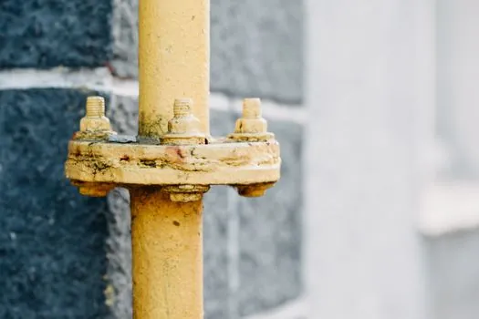
Coating failures in oil and gas service cluster in a few predictable areas. In refineries, the dominant documented failure modes are pipe-rack corrosion, tank-floor underside failure, and fireproofing delamination, almost always traced back to a coating system that was not specified for the actual service rather than to a defective batch [S4]. On buried pipelines, the main risk is FBE damage during transportation and handling, which is why SSPC-SP 10 plus holiday detection and CP backup are mandated in the spec [S1]. On offshore equipment, thermal-spray and fluoropolymer topcoats can fail at weld seams if the surface profile is not restored after welding, and at sharp edges if the DFT specification is not enforced [S3].
Measurement and inspection are part of the spec, not an afterthought: dry film thickness verification, holiday detection on immersion-rated systems, and adhesion testing on fireproofing interfaces are the three checks most often missed on rushed turnaround work. For projects where DFT verification drives acceptance, a calibrated coating thickness gauge is standard issue for the QC hold point on shop-applied FBE and for the topcoat acceptance on atmospheric systems.
Trackable Signals Going Forward
Two signals to watch over the next procurement cycle: tightening of H₂S-qualified coating lists in published engineering standards (more NACE MR0175 / ISO 15156-aligned product lists and more sour-service-qualified topcoats entering vendor datasheets), and broader specification of three-layer FBE plus abrasion-resistant overlay (ARO) for directional drilling and HDD crossings, where plain FBE is no longer the default. [S3]
A related, narrower signal: growth in field-applied, fast-cure, 100% solids liquid epoxy systems for girth-weld joints as a replacement for three-layer shrink sleeves on schedule-driven pipeline spreads, where the 100% solids chemistry is being qualified against the same CP-synergy tests used for FBE.