Open-channel flowmeters and thermal mass flowmeters occupy non-overlapping application envelopes: one targets gravity-driven open-channel liquid streams (weirs, flumes, partially filled pipes), the other targets dry, clean gas mass flow in closed pipes using thermal dispersion between two platinum RTDs [S1].
Open-channel units are dominated by ultrasonic level-based designs (38 products listed in the DirectIndustry open-channel category), followed by radar (14), bubbler (4), electromagnetic (3), Venturi (2), thermal (2), acoustic (1) and turbine (1) variants [S4]. Thermal mass flowmeter lines from suppliers such as ABB (SensaMaster FMT400) and Teledyne Hastings (HFM-D-305B) consistently publish 4-20 mA + RS-485 + digital outputs on stainless-steel in-line bodies for industrial and custody-transfer gas duty [S2][S3].
Measurement Principle and Sensor Stack
An open-channel flowmeter derives flow from a primary device (weir, flume, or known cross-section) plus a level/velocity sensor; ultrasonic non-contact is the most common 2026 sensor stack, with radar non-contact growing as a parallel option for sites with foam, steam, or high turbulence [S4]. A thermal mass flowmeter uses two platinum RTDs — one reference, one heated — and relates the cooling power required to hold a temperature differential to the gas mass flow passing the sensor, so the reading is a true mass flow rather than a volumetric one [S1].
That distinction matters at the I/O: open-channel units typically output 4-20 mA proportional to calculated flow plus HART or Modbus for level diagnostics, while thermal mass units such as the Teledyne Hastings HFM-D-305B expose 4-20 mA analog, RS-485, digital, and USB options on a 36 VDC supply for gas dosing, mixing, and custody-transfer runs [S3].
Fluid, Pipe State, and Installation Geometry
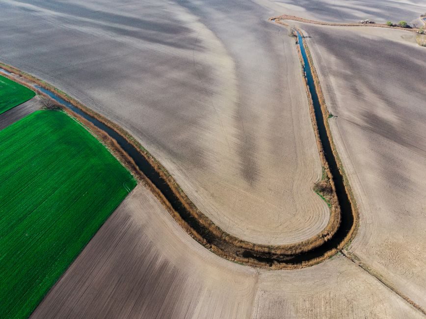
Open-channel flowmeters require a free surface, gravity flow, and a defined primary device — they fail the moment the pipe runs full or the channel geometry is altered downstream of the sensor [S4]. Thermal mass flowmeters require a fully filled, closed pipe with known cross-section, dry clean gas, and adequate straight-run length; the technology is fundamentally unsuitable for liquids, two-phase flow, or wet/dirty gas without upstream filtration [S1].
For wastewater and stormwater plants the canonical sensor pairing is an ultrasonic open-channel flowmeter on a V-notch weir or Parshall flume, sized for the expected maximum head rather than the maximum pipe diameter [S4][S5]. For gas-blending skids, burner air, and compressed-air custody transfer the canonical pairing is an in-line thermal mass flowmeter, sized on line size and expected kg/h rather than on volumetric units [S2][S3].
Accuracy, Calibration Drift, and Reference Conditions

Calibration of thermal mass flowmeters must be treated as a first-class maintenance task: the heated-RTD pair drifts with contamination, with thermal coupling changes, and with the gas property assumptions baked into the calibration gas, so field verification against a reference meter is standard practice rather than optional [S1]. Open-channel ultrasonic systems drift primarily with the primary device — siltation in a flume, weir plate damage, or submergence of the acoustic path — and their accuracy ceiling is set by the level measurement rather than the flow calculation [S4].
Thermal mass meters are commonly specified with reference conditions (typically 0 °C / 101.325 kPa or 20 °C / 101.325 kPa) and require gas composition input to convert heat-transfer reading into mass flow; a change in gas mix is an explicit re-calibration event, not a minor trim [S1]. Open-channel meters, by contrast, are referenced to a Q-h curve of the primary device and to a field-surveyed channel geometry, so an as-built survey is the equivalent of a thermal meter's gas-calibration certificate [S4].
Decision Criteria: Side-by-Side Selection Gates
The two technologies diverge on every gate a spec engineer actually writes into a purchase order, which is why side-by-side comparison belongs on the datasheet rather than in a footnote: [S1]
Open-channel flowmeter vs thermal mass flowmeter — five selection gates:
1. Fluid phase: open-channel = gravity-fed liquid with free surface; thermal mass = dry, single-phase gas in a closed pipe. If the answer is liquid with free surface, thermal mass is excluded; if the answer is closed-pipe gas, open-channel is excluded [S1][S4].
2. Output quantity: open-channel = flow rate derived from level/velocity × area; thermal mass = true mass flow independent of pressure/temperature swings [S1].
3. Primary device: open-channel = weir, flume, or known channel cross-section required upstream; thermal mass = none, but line size and gas composition must be declared [S2][S3][S4].
4. Typical I/O: open-channel = 4-20 mA + HART/Modbus for level and flow; thermal mass = 4-20 mA + RS-485 + digital/USB, examples include ABB SensaMaster FMT400 and Teledyne Hastings HFM-D-305B [S2][S3].
5. Dominant failure mode: open-channel = primary-device fouling or acoustic path loss; thermal mass = RTD contamination, coating, or gas-composition change [S1][S4].
These gates map directly to the open channel flowmeter and thermal mass flowmeter reference pages, and the same selection logic appears in the open-channel sensor-type decision frame covered in [Open channel flowmeter selection criteria](/news/open-channel-flowmeter-selection-criteria-sensor-type-primary-device-and-signal-.html).
Use Cases, Limits, and Common Misapplications
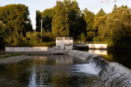
Open-channel flowmeters are the right instrument for municipal wastewater influent/effluent, plant effluent monitoring, irrigation channels, and stormwater outfalls where the line is gravity-driven and partially filled [S4]. Thermal mass flowmeters are the right instrument for combustion air, biogas, natural-gas blending, semiconductor process gases, and compressed-air custody transfer where mass flow — not volume at line conditions — drives the control loop [S2][S3].
The single most expensive misuse is installing a thermal mass flowmeter on a wet or dirty gas stream without filtration: RTD contamination shifts the calibration and is the leading cause of field return at compressor and digester sites [S1]. The mirror-image misuse is specifying an open-channel ultrasonic sensor on a full-pipe force main: as soon as the pipe runs full, the free-surface assumption breaks and the flow reading is meaningless, so force-main applications require a closed-pipe meter such as an electromagnetic flowmeter or a Coriolis flowmeter instead [S4].
Standards, Sourcing, and Sizing References
Open-channel installations lean on ISO 1438 / ISO 4359 for flumes and weirs as primary devices, while thermal mass installations lean on ISO 14511 for the calibration framework and on the supplier's gas-specific calibration certificate [S1][S4]. On long horizontal gas runs with limited straight length, the in-line thermal mass body must be ordered to the actual line size — not stepped up or down with reducers — to keep the flow profile inside the sensor's calibrated range [S2][S3].
For broader flow-class coverage inside a project portfolio, see [Turbine Flowmeter 2026 Buying Guide](/news/turbine-flowmeter-2026-buying-guide-sensor-size-output-and-fluid-class.html) for closed-pipe liquid/gas service and the [Orifice Plate Flowmeter 2026 Buying Guide](/news/orifice-plate-flowmeter-2026-buying-guide-plate-beta-tapping.html) for differential-pressure-based flow where neither open-channel nor thermal-dispersion technology fits. Working thermal-imaging and thermal-protection instrumentation around a gas skid is covered by the thermal imager and thermal relay reference pages.
Trackable signals to watch in the next 6-12 months: supplier-published updates to ultrasonic and radar open-channel firmware on DirectIndustry [S4], and any ABB SensaMaster FMT400 / Teledyne Hastings HFM-D-305B firmware or HART/Modbus option changes that move thermal mass into new gas-mix envelopes [S2][S3].