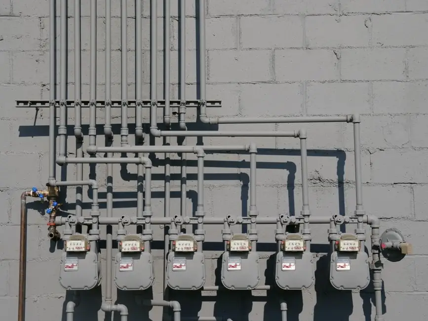
Process-pipe fittings split along two axes: what they do to the flow, and how they join to the pipe. The functional axis covers elbows, tees, reducers, couplings, caps, crosses, olets, and unions; the connection axis covers butt-weld, socket-weld, threaded, flanged, grooved, compression, and flared ends [S2][S5].
Wrought steel fittings are made from seamless pipe stock and dominate process work; large-diameter welded fittings are formed from plate per ASME B16.9 dimensional rules, while forged socket-weld and threaded fittings fall under ASME B16.11 [S2]. The standards family, not the catalog brand, sets the face-to-face, wall thickness, and pressure-temperature envelope for every line class.
Functional Categories: Direction, Branch, Size, and Termination
Elbows are the highest-volume fitting on most process skids, and 90 degree and 45 degree geometries account for the bulk of orders; long-radius (LR, centerline radius = 1.5 × nominal pipe size) elbows are specified wherever a 1.5D bend is geometrically possible, since the lower pressure drop and reduced erosion rate outweigh the extra space cost versus short-radius (SR, 1D) units [S2]. Short-radius elbows are reserved for tight routing and are commonly disallowed in high-velocity two-phase or slurry service where the inner radius accelerates flow and accelerates wear.
Tees split flow into two branches at 90 degrees; reducing tees carry a smaller branch on a larger run. Crosses intersect four lines at one point and are largely avoided in process work because they create a structurally awkward, difficult-to-support header; the four-way split is normally built from two tees [S2][S4]. Branch connections on a header that is too small for a standard tee are made with olets: Weldolet for butt-weld branch, Sockolet for socket-weld, Thredolet for threaded, Elbowlet for a 90 degree branch, Letrolet for a 45 degree lateral, and Nipolet for an integral nipple [S2].
Reducers change line size, either concentric (symmetric about the pipe centerline, used for vertical or gas service to avoid a liquid pocket) or eccentric (one face flat, used for horizontal pump suction to keep the top of the line flat and avoid an air pocket) [S2][S3]. Couplings and unions join two pipe ends; unions add a removable three-piece joint for maintenance, while couplings are typically a permanent threaded or socket-weld sleeve. Caps and plugs terminate a line; caps weld or thread onto the pipe end, plugs seat inside a female thread [S3][S4].
End-Connection Classifications: Welded, Threaded, Flanged, and Mechanical
Butt-weld (BW) ends are the default for ASME B16.9 wrought fittings in hydrocarbon and chemical service: the fitting is matched to the pipe wall, beveled, and welded with full penetration, so the joint has the same pressure rating as the parent pipe and is suitable for in-line inspection [S1][S2]. Socket-weld (SW) fittings per ASME B16.11 slide over the pipe and are fillet-welded at the socket face; they are limited to Class 3000/6000 ratings and are not used below NPS 1/2 or above systems where crevice corrosion in the annular gap is a concern, which is why many specifiers move to butt-weld at NPS 2 and above or in sour service.
Threaded connections (NPT per ASME B1.20.1, BSP variants per ISO 228) are cheap and fast but are restricted to lower pressure-temperature classes and non-toxic, non-flammable services; galling and thread-lubricant contamination are recurring failure drivers [S6]. Flanged ends (ASME B16.5 for NPS 1/2 to 24, ASME B16.47 for NPS 26 and above) pair with a gasket between raised face (RF), ring-type joint (RTJ), or flat face (FF) faces and are bolted to the mating flange with a stud bolt pattern defined by the pressure class (150, 300, 600, 900, 1500, 2500).
Grooved-end mechanical couplings (Victaulic-style, AWWA C606 for carbon steel) use a housing that clamps a groove rolled or cut into the pipe end with a rubber or elastomeric gasket; the joint tolerates some misalignment and is common in HVAC, fire-protection, and mine dewatering [S1]. Compression fittings and flared-tube fittings (SAE J514 / 37 degree flare, JIC) dominate instrumentation and small-bore tubing, where the OD of the tube is the sealing surface rather than a thread [S1][S5].
Material and Manufacturing Class: Wrought, Forged, Cast, and Mitered
Wrought fittings are formed from pipe or bar stock and are the metallurgical default for carbon steel, stainless steel, and alloy process piping; they are seamless when made from a billet, and welded when formed from plate [S2]. Forged fittings (ASME B16.11) are made by hammering or pressing heated billet into shape and are the only acceptable form for socket-weld and threaded high-pressure classes; cast fittings (ASME B16.1, B16.4) are used in lower-pressure ferrous and copper-alloy plumbing and are visually distinguishable by a coarser surface finish and parting-line flash.
Mitered elbows are field-fabricated by cutting and welding straight pipe segments at an angle; a single miter (one cut) is acceptable up to about 22.5 degrees, while multi-miter bends are limited to large-diameter low-velocity service because each miter introduces a flow disturbance and a weld subject to cyclic loading [S2]. Long-radius cold bends (1.5D to 3D) are an alternative on stainless and alloy pipe, replacing two or three weld elbows with a single bend and reducing both pressure drop and weld NDE workload.
Decision Criteria: A Side-by-Side Comparison
Specifying a fitting is a four-variable problem: rating, service, joining method, and inspection regime. The table below lines the main end-connection types against the variables a process engineer weighs during line-class assignment. [S2]
Butt-weld (B16.9) leads on pressure-temperature rating and inspectability; it is the default for NPS 2 and above in hydrocarbon, high-pressure steam, and any service where radiography or ultrasonic weld examination is required [S2]. Socket-weld (B16.11) is faster to install and tolerates misalignment, but the crevice between pipe OD and socket ID creates a corrosion trap, and most refiners restrict it to NPS 2 and below, non-sour, Class 3000 maximum. Threaded (B16.11, NPT) is lowest cost and lowest rating; it is appropriate for utility air, instrument air, and low-pressure water, and is not used for hydrocarbons above Class 2000 or for any service where a leak could create a flammable atmosphere.
Flanged joints score on maintainability; a spacer ring or spectacle blind lets you isolate and blank a line without cutting, which is why flanges are standard at equipment connections, valve ends, and tie-in points. Grooved mechanical couplings win on speed of field assembly and tolerance of minor pipe misalignment, but their pressure-temperature rating is capped by the elastomeric gasket (EPDM up to about 120 degrees C, HNBR higher) and they are not used in hydrocarbon refining above Class 300. Compression and flared tube fittings are the correct answer for instrumentation and small-bore hydraulic lines because the tube, not a thread, is the pressure boundary [S1][S5].
Selection Discipline and Common Failure Modes

For pipe-fitting sourcing decisions, the upstream pipe material is the starting constraint: stainless steel lines pair with stainless or low-carbon stainless fittings to avoid galvanic dissimilar-metal welds, and sour service (NACE MR0175 / ISO 15156) imposes hardness caps, mandatory low-alloy chemistry, and welding procedure qualification that rule out generic stock [S2]. The line-class document then fixes the pressure class, the corrosion allowance, and the NDE requirement, and the fitting is selected inside that envelope rather than the other way around.
Common failure modes map directly to misclassification. Threaded joints leak because of under-torque, over-torque, or thread sealant incompatibility with the service fluid. Socket-weld joints crack at the fillet toe under thermal cycling, especially in hot hydrocarbon lines that were not stress-relieved. Grooved couplings lose pressure containment when the gasket ages or the housing bolts loosen, and the failure is rarely visible without a full system pressure test. Flanged joints leak at the gasket when the bolt torque is uneven or the flange face has been damaged during handling.
For an engineer working out of the pipe fitting family of pages, the same rule applies across the catalog: the dimensional standard (B16.9, B16.11, B16.5) defines the geometry, the material standard (ASTM A234, A420, A403, A105, A182) defines the metallurgy, and the inspection standard (ASME B31.3 process piping, B31.1 power piping, B31.4 hydrocarbon pipeline) defines the acceptance criteria. Each of those three layers is independent, and a wrong choice in any one of them downgrades the entire joint.
Sourcing, Standards Map, and Related Reading
Wrought carbon steel butt-weld fittings to ASME B16.9 from common ASTM grades (A234 WPB for hot service, A420 WPL6 for low-temperature, A403 WP304/316 for stainless) are stocked in the standard NPS range; forged socket-weld and threaded fittings to ASME B16.11 ship in A105 carbon and A182 F316 stainless, while cast iron fittings per ASME B16.1 (gray) and B16.4 (malleable) cover the plumbing-grade side. Ductile iron AWWA C110 / C153 fittings carry the water and wastewater spec line. [S2]
For context on how the pipe itself is classified, the stainless steel pipe types and metallurgical families reference covers the upstream stock most wrought fittings are machined from. The broader stainless steel pipe pros, cons, and selection map article walks through when stainless is the right call versus carbon steel lined pipe. Where the joining method shifts from welded to mechanical, the grooved and compression categories overlap with the broader piping fitting family, which is the better starting point for HVAC and fire-protection specifiers.
The verifiable next node for any project is the line-class document: pressure class, corrosion allowance, NDE percentage, and the material specification number. Once those four fields are locked, fitting selection reduces to matching the dimensional standard (B16.9, B16.11, B16.5) and the material grade (A234, A420, A403, A105, A182) to the same envelope. The two trackable signals that should be watched are revisions to ASME B16.9 dimensional tables and changes to the ASTM A234/A403 supplementary requirements, both of which move the catalog every 2 to 3 years.
For component-level specifications, see construction machinery and equipment.