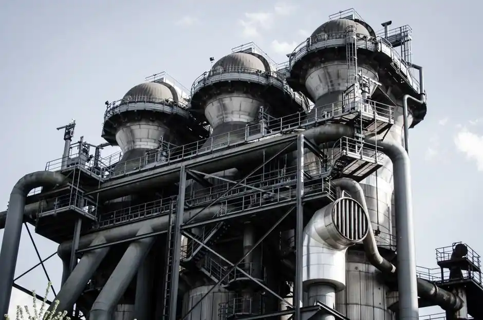
A planetary reducer, in which a central sun gear drives planet gears orbiting inside a ring gear, delivers 94-98% efficiency across a 3:1 to 1000:1 ratio range while keeping input and output shafts coaxial, the architecture that process engineers most often specify for steel mill rolling-mill and conveyor drives [S2].
Steel mills run rolling stands, cooling beds, slab conveyors, billet handlers, and furnace charging systems under continuous heavy shock load, so the spec conversation moves immediately from ratio to torque density, thermal margin, and the gearbox's ability to take peak overloads without lubricant failure [S1].
Why Planetary Architecture Fits Rolling-Mill Duty
Planetary gearboxes are commonly used in steel mills because they provide extremely high torque capacity in a compact footprint, with load shared across three or more planet gears contacting the sun and ring simultaneously [S1]. That load sharing is the structural reason a planetary unit of a given frame size routinely out-torques a parallel-shaft helical unit of the same OD in mill stands, coilers, and heavy-duty conveyor drives [S1].
Coaxial alignment matters on a mill floor where space behind the stand is consumed by roll-change hydraulics and descalers; the input/output on the same axis lets the drive train sit in a narrow envelope without right-angle bevel sections eating clearance [S2]. A typical 29:80 tooth pairing in a single planetary stage gives a 2.76:1 reduction, and stacking two or three stages in the same housing pushes the practical range up to 1000:1 for low-speed table rolls and pinch rolls [S2].
Decision Criteria: Torque Density, Heat, and Shock
For a hot-strip mill or plate mill stand, the first pass screen is service factor against peak torque, not nameplate ratio, and the second pass is thermal rating at the ambient temperature around the stand, where gearbox housings commonly see 60-80 °C radiant heat from adjacent billets [S1]. A planetary unit in this service is usually specified with a synthetic PAO or polyglycol lubricant rated above 100 °C sump, an oil cooler or fan-on-shaft option, and sealing that holds back scale dust and cooling-water spray [S1].
Where the same mill also runs cold-rolling or finishing lines, backlash and torsional stiffness become the differentiators, so single-stage helical-planetary units below 5 arc-min are common on coiler mandrels and tension reels, while coarser multi-stage units (3-10 arc-min) are accepted on runout tables and cooling-bed drives where positioning is non-critical [S4]. Neugart's published band of 94-98% efficiency for planetary reducers, versus 90-95+% for bevel units and 94-98% for helical units, is the headline number engineers quote when justifying the premium on rolling-mill main drives [S2].
Planetary vs Bevel vs Helical: Steel Mill Comparison
The three architectures engineers most often compare for steel mill auxiliary drives line up against four practical criteria: ratio range, efficiency, axis layout, and shock load tolerance. Planetary units cover 3:1 to 1000:1 at 94-98% efficiency on a coaxial axis layout, with the highest torque density of the three, which is why they are the default on rolling stands, coilers, and heavy conveyors [S2].
Bevel helical units cover 1:1 to 5:1+ at 90-95+% efficiency on a right-angle axis layout, with good continuous-duty performance but lower torque density, fitting cooling-bed drives and conveyor transfers where the drive has to live in a side pocket rather than behind the roll [S1]. Parallel-shaft helical units cover 1:1 to 10:1+ at 94-98% efficiency with smooth, quiet operation, which is why engineers keep them on material-handling conveyors and transfer tables rather than on the shock-loaded main stands [S2].
For a complete conveyor-driven auxiliary train in a mill, the gearbox selection for material handling spec map covers the helical and bevel-helical options in more detail, and the wind-power gearbox replacement economics piece is a useful contrast case for high-ratio, high-torque planetary duty outside the mill.
Stages, Ratios, and Frame Sizing for Mill Stands
Single-stage planetary units typically deliver ratios in the 3:1 to 10:1 window and are the right call when the upstream motor runs at 1500-1800 rpm and the downstream roll needs 200-500 rpm, for example on a roughing stand pinch roll or a runout table roller [S2]. Two-stage planetary units cover 15:1 to 100:1 in one housing, which is the common configuration for coiler mandrels and tension reels where the motor sits well away from the working roll.
Three-stage planetary units are pushed into service for ratios above 100:1 up to the published 1000:1 ceiling, and are usually reserved for slow-speed table rolls, screw-down mechanisms, and furnace-charging machines where the duty cycle is intermittent rather than continuous [S2]. The trade-off is straightforward: each added stage costs roughly 1-2 percentage points of efficiency, so a 1000:1 three-stage unit at 92-95% mechanical efficiency is normal, and the waste heat shows up in the thermal sizing step rather than in the ratio step [S2].
Who a Planetary Reducer Is For, and Who It Is Not For

Planetary reducers are the right call for steel mill applications with high torque, compact envelope, and shock loading, including rolling mill stands, coiler mandrels, heavy slab conveyors, and cooling bed transfers, where their coaxial layout and load-sharing tooth contact handle the duty without right-angle gear sets [S1]. They also fit servo-driven positioning axes on mill automation, where the planetary reducer architecture and the harmonic reducer option are usually weighed against backlash and stiffness budgets rather than raw torque.
They are not the right call for legacy spur-gear main drive stands where the existing motor and foundation are sized for a parallel-shaft drop-in, for low-ratio right-angle fan or pump drives where a bevel-helical unit is cheaper, or for any application where contamination from mill scale and water would overwhelm the planet-carrier sealing, in which case a worm reducer or enclosed bevel unit may be the more honest answer even at lower efficiency [S1].
Lubrication, Cooling, and Common Failure Modes
Mill-floor planetary failures cluster around three modes: lubricant breakdown near furnace-area drives, seal failure under scale and water ingress, and planet-bearing spalling from shock overloads that were not folded into the service factor. A standard mitigation is to upsize the gearbox service factor by 1.25-1.5 over the calculated peak torque, fit an oil cooler or fan-on-shaft accessory, and specify sealed-for-life bearings in the planet carrier [S1].
For a complete reducer topology comparison including gear reducer, cycloidal reducer, and RV reducer architectures, the mill spec should treat the choice as a thermal-and-shock decision, not a ratio decision, because the ratio is the easy parameter to meet and the heat-and-shock margin is the parameter that determines mean time between failures on a hot-strip mill [S2].
Manufacturer Field and Trackable Sourcing Signals
On the steel mill side, the manufacturer field that the [S1] buyer guide names includes Nord Drivesystems and Radicon, both with heavy-duty industrial housings and high-torque ratings, plus the broader helical, bevel-helical, and planetary ranges that Chinese OEM catalogues such as the Techman automation line are filling at the lower-price end with helical, right-angle, and cryogenic planetary options down to -196 °C for ancillary mill equipment [S3].
Two trackable signals to watch through the rest of 2026 are the publication of updated AGMA service-factor tables for mill duty, and the first wave of ISO 6336-aligned thermal-rating curves from the major planetary OEMs, both of which would let mill engineers move from nameplate-ratio selection to verified thermal-and-shock selection without a vendor-specific safety factor layered on top.