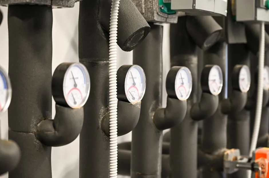
The power end of a plunger pump is the mechanical assembly that takes rotational input from the driver and converts it into linear reciprocating motion of the plungers, housing the crankshaft, connecting rods, crossheads, bearings, lubrication system, and structural frame [S1].
The fluid end is strictly the wetted zone where liquid is sucked into the pump on the suction stroke and forced out under pressure on the discharge stroke, containing the fluid end block, suction and discharge valves, packing, plungers, and manifolds [S1]. On a given pump, the same power end can be paired with a triplex, quintuplex, or hex fluid end simply by changing the number of plungers and the block geometry [S5].
What the power end actually contains
The power end of a reciprocating mud pump or frac pump is built around a crankshaft supported in rolling-element or plain bearings, with connecting rods linking each crank throw to a crosshead that slides in a guide; the crosshead in turn pushes the plunger rod through a stuffing box into the fluid end [S6]. Splash or pressure lubrication is fed to bearings, crosshead pins, and the crosshead-to-rod interface, and the whole assembly is enclosed in a cast or fabricated frame rated for the continuous dynamic loads of the service [S6].
Service work on the power end centers on bearings, bearing housing fits, crankshaft journals, crosshead seals, and lube circuits, and can be done with the fluid end in place as long as suction and discharge are isolated and the driver is locked out, per the inspection protocol that requires isolation, depressurization, and lockout before any liquid-end work begins [S3]. Torque transmission is the design driver: on a five-throw quintuplex the crank throws are spaced 72° apart, while a six-throw hex pump uses 60° spacing to lower discharge pulsation, and those same phase angles are fixed by the power-end geometry, not by the fluid end [S5].
What the fluid end actually contains
The fluid end is the wetted hydraulic module, typically a forged monoblock that houses suction and discharge valve assemblies, packing, plungers, suction and discharge manifolds, and the cross bores that route flow between chambers, and its function is to manage fluid intake, compression, and discharge at the rated discharge pressure [S5]. In oilfield service that pressure commonly runs 5,000–15,000 psi for triplex fluid ends, up to 20,000 psi for quintuplex fluid ends, and up to 25,000 psi (≈172.4 MPa) on hex pump fluid ends used in continuous high-rate fracturing [S5].
Standard fluid-end body materials listed for modern oilfield pumps are 35CrMo, 4130, or 17-4PH forged steel, with valve seats in tungsten carbide or 17-4PH, plungers in ceramic-coated or nitrided alloy steel, and sealing via V-packing or Chevron stacks, and the assembly is designed to API 674 or API 7K compliance where the datasheet is invoked [S5]. For aggressive service such as sand-laden fracturing or acidizing, 17-4PH stainless or Inconel 625 are common, sometimes with nickel or tungsten carbide overlays, and for offshore hex pumps duplex stainless ASTM A182 F51/F53 is a typical body choice [S5].
Material and lubrication rules that differ between the two ends
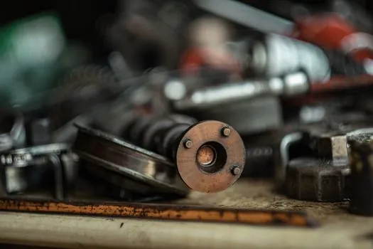
Because the power end is a lubricated machine, its bearings, crosshead shoes, and rod packings run in oil and are selected for fatigue life, while the fluid end is a pressure boundary that runs in the pumped fluid, so its material and surface-engineering choices follow corrosion, erosion, and pressure-containment rules instead [S1]. For pumped fluids that do not have lubrication qualities (seawater, fresh water), the plungers themselves must be force-fed lubricated through a separate circuit, and the lubrication tubing for that circuit is specified as 316 stainless steel to avoid contamination and corrosion failure [S3].
For non-lubricating service a lantern ring is required between two sets of packing rings immediately below the lubrication point on the packing box so the lubricant actually reaches the sealing interface; without that ring the packing runs dry and wears out prematurely, which is a fluid-end-side failure mode, not a power-end one [S3]. Packing type on the fluid end is typically square-cut or V-ring, while the power end uses splash, pressure, or plunger-rod lubrication as a separate line item on the pump datasheet [S3].
Inspection, repair, and the rebuild decision
Inspecting the liquid end of the pump means inspecting the valves, packing, and plungers, and that work cannot be performed unless the pump has been isolated, depressurized, and the driver locked out, even after isolation, since pressure can remain trapped in valve chambers [S3]. Procedure steps include removing and disassembling all valves, replacing worn or broken parts, checking seating surfaces for smoothness, cleaning valve cavities before reassembly, micrometering plunger diameter at several points (especially at the packing contact zone), replacing packing rings on every liquid-end overhaul, and inspecting the packing box bore, with a stainless steel sleeve considered if the bore is worn [S3].
On frac operations the rebuild-or-replace call is driven by direct exposure to high-pressure fluid, proppant, and pressure-cycle fatigue, so the fluid end is treated as a wear part with finite service life, while the power end is rebuilt only on much longer intervals and judged on bearing and crankshaft condition rather than pressure-cycle count [S7]. The pump datasheet captures this split by listing power-end-bearing type and fluid-end pressure rating (typically 120% of design discharge pressure) as separate line items [S3].
How the same power end pairs with different fluid ends
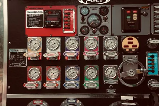
On a plunger mud pump the power end and fluid end are independent subassemblies bolted to a common frame, and swapping the fluid-end module does not require a new power end, which is why one frame can be sold as triplex, quintuplex, or hex simply by changing cylinders, plungers, and the fluid end block [S2]. A triplex fluid end uses three plungers at 120° phase spacing, the standard compact configuration for drilling mud circulation, water injection, and low-to-medium-pressure fracturing, while a quintuplex fluid end uses five plungers at 72° phase spacing for smoother flow in high-pressure fracturing and acidizing, and a hex fluid end uses six plungers at 60° spacing for ultra-high-pressure continuous pumping at 20–25 BPM [S5].
For comparison, a triplex block in 35CrMo/4130/17-4PH typically runs 5,000–15,000 psi with V-packing or Chevron seals to API 674 or API 7K; a quintuplex block in 17-4PH or Inconel 625 with optional nickel or tungsten carbide overlays runs up to 20,000 psi for corrosive acidizing fluids; a hex block in alloy steel or duplex stainless ASTM A182 F51/F53 with a dual-chamber cooling system runs up to 25,000 psi for offshore stimulation and long-duration pressure pumping, all on the same basic power-end architecture with more throws added to the crankshaft [S5].
Where plunger pumps fit, and where they do not
Plunger and packing technology is selected when high pressures (800–1,000 psi / 55–69 bar and higher) and lower flow rates are required, because the discharge pressure pushes on the front of the packing and compresses it against the smooth plunger surface to seal off leakage; below that pressure range there is not enough flow pressure to assist the seal, sand and abrasive solids lodge between packing rings and plungers, and the assembly wears out rapidly [S2]. The same logic is why triplex, quintuplex, and hex fluid ends all assume high-discharge-pressure service and add more plungers, not larger ones, when higher flow is needed at the same pressure class [S5].
Plunger pumps are not the right tool for low-pressure, high-flow mud pumping on a directional boring rig, where piston/liner pumps running below about 1,200 psi (83 bar) are preferred because the operator can no longer adjust packing to slow leakage on a plunger pump once sand ingestion starts cutting the seal, and a field conversion kit to switch from plunger to piston technology is a recognized retrofit when the plungers are no longer serviceable [S2]. Practical reading of the materials in this article, including the data sheet lines and the inspection protocol, is collected on the plunger pump reference page for engineers writing or reviewing pump specs.
Watch the datasheet for the 120%-of-design-discharge-pressure line on the fluid end, the API 674 or API 7K compliance row on the same datasheet, and the V-ring vs square-cut packing selection, because those four items, plus the 316 SS lubrication tubing call-out for non-lubricating service, are where power-end and fluid-end specifications most often get crossed or omitted, and a quarterly look at field failure photos of fluid-end blocks will surface wear and crack patterns faster than any single inspection ticket [S3][S5].
For the relevant spec sheets and selection criteria, see fluid coupling, and construction machinery and equipment.
Background reading: Comparative vs Absolute Measurement with a Dial Indicator: Resolution, Standards, and.