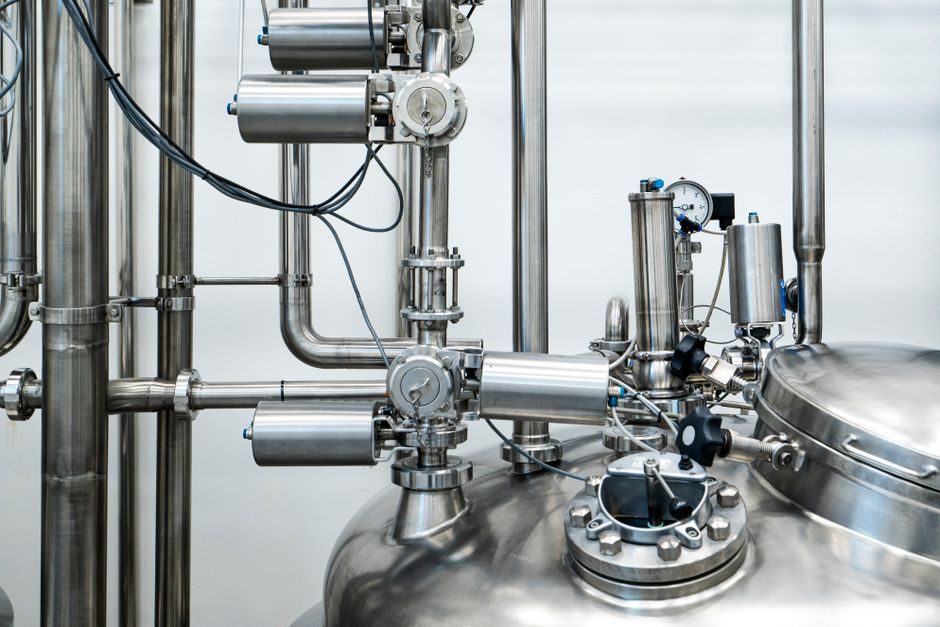
Specifying a pneumatic conveying line is a phase-mode decision first and a hardware list second: dilute-phase lean systems typically run at solids-to-air mass ratios of roughly 1–10 kg/kg with high air velocities, while dense-phase plug or fluidised systems push that ratio to 30–80 kg/kg at low velocity, and the operating envelope changes by an order of magnitude between them [S2].
For a 1–50 t/h powder or granulate duty, the design funnel begins with material properties (bulk density, particle size, dB, friability, hygroscopicity), then conveyance distance and bend count, then mode (negative-pressure vacuum, positive-pressure, or a combined pull-push), and only then does the engineer size the pneumatic conveyor, the rotary or pneumatic actuator valves at the inlet, and the receiver vessel [S1][S2].
Phase mode as the master decision: dilute, semi-dense, dense
Dilute-phase conveying covers the bulk of OEM catalogue offerings, with 9 manufacturers and 14 products listed on DirectIndustry's powder pneumatic conveying index, where Air-Tec and ANDE-class suppliers position themselves in the lean-phase general-purpose segment [S1]. The lean-phase window is the engineering default: air velocity roughly 15–25 m/s for non-fragile granular plastics, cement, fly ash and alumina, and a pneumatic cylinder-driven blow tank or a screw feeder as the inlet device.
Dense-phase (plug-flow, fluidised, or pulse) targets friable, abrasive or contamination-sensitive powders — flour, titanium dioxide, PVC, PFA, catalysts — and runs at velocities closer to 5–10 m/s but at much higher line loading, so the same mass flow needs a smaller pipe and less filter area, at the cost of longer blow tanks, booster rings and tighter pneumatic fitting classes for the higher pressure drop.
DirectIndustry's 14-product catalogue is a useful proxy for the OEM pool: it is dominated by dilute-phase positive-pressure blow-tank designs and a smaller cluster of vacuum/lean-phase units, and ANDE metallurgical's solution page frames its range around the same dilute/dense split with custom pipe and rotary-valve packages [S1][S4].
Solids-loading ratio and the air-velocity window
The dimensionless lever in pneumatic conveying is the solids-to-air mass ratio (µ, sometimes written kg solid / kg air). Dilute-phase sits in the µ ≈ 1–10 range, semi-dense in roughly 10–30, and dense-phase in 30–80 or higher with a plug booster; doubling µ for the same mass flow roughly halves the air requirement and the pipe cross-section, but raises the risk of saltation, plug collapse and pipe wear [S2].
Saltation velocity — the air speed below which particles drop out of suspension — sets the lower operating line, and is typically 0.6–0.8 × pickup velocity. For 100–500 µm granules at 800 kg/m³, saltation lands in the 12–18 m/s window; for fine cohesive 10–50 µm powders it falls to 4–8 m/s, which is why dense-phase and not lean-phase is the only viable mode below 50 µm without line-blocks.
Bend count and total equivalent length matter more than straight-run length: each long-radius 90° elbow adds roughly 8–15 equivalent pipe metres of pressure drop, and an abrasive service (fly ash, sand, alumina, sintered ore) can chew through a standard 3-mm 16Mn or Q235 bend in 12–24 months — which is why OEM catalogues list hardened elbows as a separate option, not a default [S1][S2].
Pressure/vacuum mode and the air mover choice

Three topologies compete: negative-pressure (vacuum) systems pull material up to about 50 m horizontally with a multi-stage roots blower or a water-ring pump, positive-pressure systems push from a blow tank or screw feeder through 100–600 m with a roots blower or screw compressor, and pull-push combinations chain both with an intermediate receiver [S2].
Receiver selection is dictated by duty cycle: for batch blow-tank feeding at 4–12 cycles/hour, a 0.5–6 m³ ASME-stamped pressure vessel with a top-mounted dome valve and a bottom pneumatic actuator disc is the standard; for continuous lean-phase, a cyclone + bag-filter receiver is the workhorse, and the filter area is sized at 0.5–1.0 m² per 1,000 m³/h of air at ≤ 2.5 mg/m³ emission targets aligned with typical regional PM limits [S2].
Particle behaviour, material class and pipe/wear decisions
Particle size governs minimum pipe diameter through the rule of dB / D ≥ 20–30 to limit dune formation, which means a 50 µm cohesive powder needs a DN 80–100 minimum line, a 1 mm granulate is fine in DN 50, and a 5 mm pellet can drop to DN 40 — and the smaller the bore, the more a pneumatic fitting tolerance stack-up (compression ferrule, V-band clamp, or grooved coupling) starts to dominate leakage behaviour.
For high-temperature services (up to 400 °C in cement, power, and steel-mill fly-ash lines), refractory-lined steel pipe and stainless transitions are the norm, and the conveying-air temperature window narrows to 80–150 °C for polymer or food contact; the [pneumatic conveying design guide] literature flags this as the single largest source of mis-specification, where a 20 °C rating margin up or down can flip the mode from dilute to dense or back again [S2].
Comparison: dilute-phase vs semi-dense vs dense-phase on four spec gates
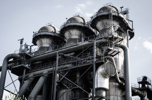
On the four decision gates that drive every pneumatic conveying line — solids-to-air ratio (µ), air velocity, distance/turn tolerance, and abrasive-duty pipe cost — the modes line up as follows: dilute-phase posts µ ≈ 1–10 kg/kg at 15–25 m/s and tolerates 20+ long-radius bends over 100–500 m, but penalises abrasive wear (standard 3 mm Q235 bends last 6–18 months on fly ash); semi-dense posts µ ≈ 10–30 at 10–18 m/s, covers 200–400 m with up to 10–15 elbows, and requires hardened bends as a baseline; dense-phase posts µ ≈ 30–80 at 5–10 m/s, manages 50–250 m with up to 8–12 elbows under pulse booster, and demands basalt or SiC-lined bends plus dehumidified or inert air [S2].
For a 10 t/h alumina transfer over 250 m with 6 long-radius elbows, dilute-phase is the simplest spec but the most wasteful on air and pipe wear; semi-dense halves the air volume at the cost of longer blow-tank cycles; dense-phase runs the smallest blower, the smallest pipe, and the most expensive wear package — and the economic crossover (CAPEX + 5-year wear parts) typically lands at 150–200 m equivalent length for a single-vessel, single-blower installation [S2].
Who dilute vs dense is for, and the failure modes to engineer against
Dilute-phase fits plants that handle non-cohesive granular materials in 100 µm–5 mm window, run short- to mid-distance transfers (≤ 500 m), and need a fast start-up with a low CAPEX line; it is the wrong answer for 10 µm cohesive powders, 600 m+ single runs, or any ATEX/IECEx Zone 20/21 dust-explosive service where minimising air volume and the resulting dust cloud becomes a safety requirement in its own right [S1][S2].
Dense-phase is built for friable pigments, abrasive ore, food and pharma powders, and long-run high-tonnage transfers where air economy outweighs capex, but it is the wrong answer for non-friable 1–5 mm granules that need to stay unbroken — and the dense-phase failure mode is plug collapse in vertical or near-vertical sections, not line blockage as in dilute-phase, so a different receiver sizing and a different booster topology are required [S2].
The same constraint logic drives overhead conveyor sizing for non-pneumatic alternatives, where the decision tree between pneumatic and mechanical conveying is set by friability, distance, and material class in exactly the same way. For power-plant fly ash and dry scrubber service specifically, the dilute vs dense phase trade-off for power generation discussion extends the same spec gates to the unique ash-handling envelope of coal- and biomass-fired units.
Standards, sourcing reality and procurement gates
Pressure-vessel receivers in pneumatic conveying are governed by ASME BPVC Section VIII (Division 1 for non-fired) for US-built skids, with the EU equivalent EN 13445 and Chinese TSG 21 covering the same scope; blow tanks and air receivers are typically U-stamped or PED/CE-marked, and that stamp is the most common procurement-line reject point on a Chinese-built skid headed for an EU or US plant. [S1]
ATEX 2014/34/EU and IECEx certification cover the dust-explosive envelope when the conveyed powder has a Kst > 0 bar·m/s and the equipment is destined for Zone 20/21/22 — the majority of powder-conveying builds since 2020 carry dual ATEX + IECEx marking so the same skid ships to a US Gulf plant and a German chemical site without re-engineering [S1][S2].
Sourcing reality on DirectIndustry's 14-OEM pool: lead time for a configured blow-tank + blower + receiver skid in the 5–20 t/h range sits at 16–28 weeks ex-works Asia, with the critical-path item being the roots blower or screw compressor rather than the pipe spool; spare-bend wear packages are usually quoted separately at 8–12% of skid capex, which is the number to anchor a 5-year total-cost-of-ownership argument when dilute- and dense-phase bids are being compared side by side [S1][S4].
Selection map: a 60-second decision sequence
Step 1: classify the powder by µ, dB, friability, abrasiveness, hygroscopicity and explosibility; if Kst > 0 bar·m/s, ATEX/IECEx Zone 20 marking is mandatory for any EU and most Asia-Pacific builds [S2].
Step 2: pick the mode — dilute if non-cohesive granular and ≤ 500 m, semi-dense if 10–30 kg/kg is achievable and 200–400 m, dense if cohesive, abrasive, friable, or hygroscopic.
Step 3: size the air mover — roots blower for ≤ 1 bar(g) duty, screw compressor for 2–4 bar(g) dense-phase, and pick the pneumatic fitting class (compression, V-band, or grooved) to match the rated ΔP.
Step 4: size the receiver — blow tank volume from the duty cycle (typically 0.5–6 m³), filter area from the air-flow at the agreed emission limit, and the pneumatic cylinder or rotary actuator on the dome valve from the cycle rate and the back-pressure.
Step 5: run the wear economics — dilute on abrasive service means 6–18 month bend replacement and a 4–6 mm wall upgrade; dense means basalt or SiC liners with a 3–5 year life and a 12–18% capex premium that is recovered by 200 m equivalent length.
A trackable next signal: the DirectIndustry powder pneumatic conveying index updated its 14-OEM product count on 31 May 2026 [S1], and ANDE metallurgical's solution category page was last revised 3 July 2026 [S4]; a third signal to watch is the Pneumatic Conveying Design Guide reference on ScienceDirect, last indexed 28 September 2025, which remains the consensus methodology source for phase-mode and saltation-velocity calculations [S2].