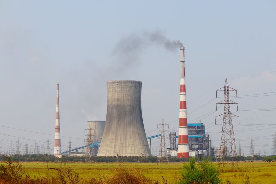
In a coal-fired or biomass-fired power plant, pneumatic conveying is the workhorse for moving dry fly ash, bottom ash, FGD gypsum, limestone, sorbent and pulverised fuel from the boiler island to storage silos, truck loading or bagging stations.
Selection splits cleanly into two families: dilute-phase (also called lean-phase, suspension flow) at solid-to-air mass ratios typically below 25:1, and dense-phase at ratios above 25:1, often 40-200:1, with slug flow or fluidised regimes. For most utility boilers under 30 t/h per line, dilute-phase positive-pressure systems remain the engineering default, while dense-phase units are specified only when material is abrasive, friable, hot, or when minimum conveying velocity would otherwise damage particles [S2].
Phase, Pressure Mode and Material Compatibility
Dilute-phase positive-pressure (PD blower or screw pump driven, conveying velocity 15-30 m/s) suits dry, non-friable fly ash and limestone up to roughly 5-30 t/h, and pairs naturally with standard 4-6 bar industrial air supplies commonly available at the plant air ring. Dilute-phase vacuum systems (15-25 m/s) are picked when the pickup point is too dispersed for a single blow feeder — multiple ash hoppers, electrostatic precipitator hoppers, baghouse hoppers — and the conveying line must gather material before discharge to a single silo, which is a common layout on 200-800 MW units [S2][S4].
Dense-phase low-velocity conveying (3-8 m/s, often via a pressure vessel or blow tank, designed per ASME BPVC Section VIII Div. 1) is used for filter cake gypsum from wet FGD, dewatered pond ash, or alumina sorbent where particle attrition must stay below 1-3 wt% degradation. A full breakdown of phase, pressure mode and material compatibility is the natural next read once a plant engineer has shortlisted the duty class.
Critical Spec Gates for Coal-Plant Duty
Six spec gates decide the build: (1) throughput in t/h, (2) material bulk density (fly ash 0.5-0.9 t/m³, FGD gypsum 0.7-1.0 t/m³, raw limestone 1.4-1.6 t/m³, pulverised fuel 0.5-0.7 t/m³), (3) particle size distribution — fly ash typically 1-300 µm with d50 around 20-50 µm, gypsum often 0-3 mm, (4) conveying distance and number of bends, (5) feed and discharge elevation, and (6) abrasive index or particle hardness (Mohs 3-4 for gypsum, 5-7 for fly ash with high unburned carbon and bottom-ash fraction) [S2][S4].
Air supply sizing is the second gate. Dilute-phase pneumatic conveying typically demands 0.025-0.06 Nm³/min of free air per kg of material conveyed, with line pressure 0.3-0.6 bar(g) for the bulk flow plus 0.2-0.3 bar per 100 m of pipe. Dense-phase blow tank systems consume less volume per kilogram (often 0.005-0.015 Nm³/min per kg) but require 2-4 bar(g) vessel pressure and full ASME-coded pressure-vessel documentation [S2][S5].
Dilute-Phase Positive vs Vacuum vs Dense-Phase: Head-to-Head
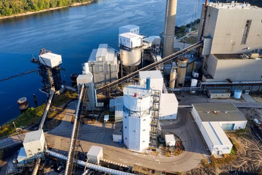
On the three criteria that drive power-plant purchase orders — capital cost per t/h, plant-air compatibility, and particle degradation — the comparison lines up as follows. Dilute-phase positive-pressure systems sit at the lowest installed cost, integrate directly with the existing 5-7 bar(g) instrument-air or service-air ring without a dedicated booster, and cause 3-5 wt% attrition on fly ash, which is acceptable for most disposal routes [S2][S4].
Dilute-phase vacuum systems (e.g. roots-blower driven exhauster at 400-500 mbar negative) cost 20-35% more in installed capital, need a vacuum-rated cyclone receiver and a sealed rotary valve or filter receiver at the silo, and are the only sensible option when the pickup points are scattered. Dense-phase pressure-vessel systems are the most expensive — typically 1.8-2.5× the cost of an equivalent dilute-phase positive line — but reduce conveying velocity to 3-8 m/s, keep particle attrition under 1-2 wt%, and allow long horizontal runs (up to 800-1500 m) with a single blow tank cycle [S2][S5].
Component Stack: Blowers, Tanks, Cyclones, Lines, Filters
A 1 mm ceramic wear patch on the outer radius of each bend doubles bend life when handling abrasive fly ash [S2][S4].
Dense-phase systems add a pressure-rated blow tank (ASME-stamped, 0.5-6 m³ typical), an air-cushion or booster ring on the bottom cone, a top-mounted pinch valve or dome valve for material feed, and often a top-blow supplementary air line to keep the column fluidised. A pneumatic silencer on the blow-tank vent line is mandatory once discharge pressure exceeds 2 bar(g), both for OSHA 29 CFR 1910.95 noise compliance (typically 85 dBA at 1 m boundary) and to keep the receiving filter from lifting [S2][S3].
Safety, Standards and Documentation Required
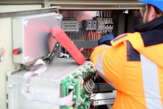
Power-plant conveying is a YMYL-duty class — a wrong filter spec on a fly-ash silo can dust-load an entire boiler house. The minimum documentation gate includes: pressure-vessel data report for any tank above 0.1 m³ and 0.5 bar(g) (ASME BPVC Section VIII Div. 1), the local PED 2014/68/EU equivalent for EU sites, blower performance curves verified to ISO 1217, and conformity to the dust-explosion protection rules of NFPA 654 in US plants (and IEC 60079 series / ATEX 2014/34/EU and ATEX 1999/92/EC in EU plants) wherever the bulk is classified as a combustible dust [S2][S5].
For ash hoppers and baghouse discharges, the rotary valves or screw feeders feeding the pneumatic line must be specified to handle the upstream temperature — fly-ash hoppers above the air preheater commonly sit at 150-250 °C, so the rotary valve is usually water-cooled or purged with clean instrument air. The downstream pneumatic fitting and compression-coupling selection on the conveying line must match the thermal class too, otherwise the epoxy-coated ductile-iron couplings will creep within months on a 200 °C service [S2][S4].
Limits, Failure Modes and What to Avoid
Three failure modes dominate pneumatic-conveying incidents in power plants: line plug from under-aerated fine ash, filter receiver bag failure from moisture-laden ash, and cyclone wear-through from unburned-carbon grit. The line-plug fix is almost always saltation velocity being misread — for fly ash, the design conveying velocity should be at least 1.5-2.0× the saltation velocity, which itself runs 10-18 m/s depending on d50 and moisture. Operating below that line will plug within a shift [S2][S5].
The filter-receiver fix is upstream: a hot-gas take-off above 110 °C will ignite deposited ash on filter bags (especially on dust-loadings above 800 g/m²), so the receiving hopper should vent back to the main filter house or a dedicated hopper with miniburst panels.
Sourcing Map and 2026 Lead-Time Reality
European deliveries sit at 18-26 weeks for dilute, 26-40 weeks for dense, with rotary valves and blow tanks as the critical-path items. North American supply is shortest for standard tri-lobe blowers (8-12 weeks) and longest for ASME-stamped pressure vessels (24-36 weeks) [S3][S4].
Process-engineer advice: write the spec around the material data sheet and the air-supply envelope, not around a preferred OEM; the same project has been built with Progressive Products blowers, Quickdraft vacuum systems, and Pneuvay-distributed Piab vacuum conveyors on the same plant in the past five years [S1][S3][S5]. A related 2026 connector supply chain 2026 pricing and lead-time read is useful for the I/O and power wiring side of the control panel, and a pneumatic actuator cross-reference helps if the diverter valves are pneumatic rather than electric.
Trackable signal: ASTM C618 Class F fly ash market tightness through 2026-Q4 will push more utility plants toward dense-phase gypsum handling retrofits, which is the first spec to revisit if your ash-handling RFP is still being drafted. A second node worth watching is the next IEC 60079-0 maintenance cycle — explosive-dust zone classifications for ash hoppers in coal plants are periodically re-issued and the receiving silo vent filter dust-class rating must follow.