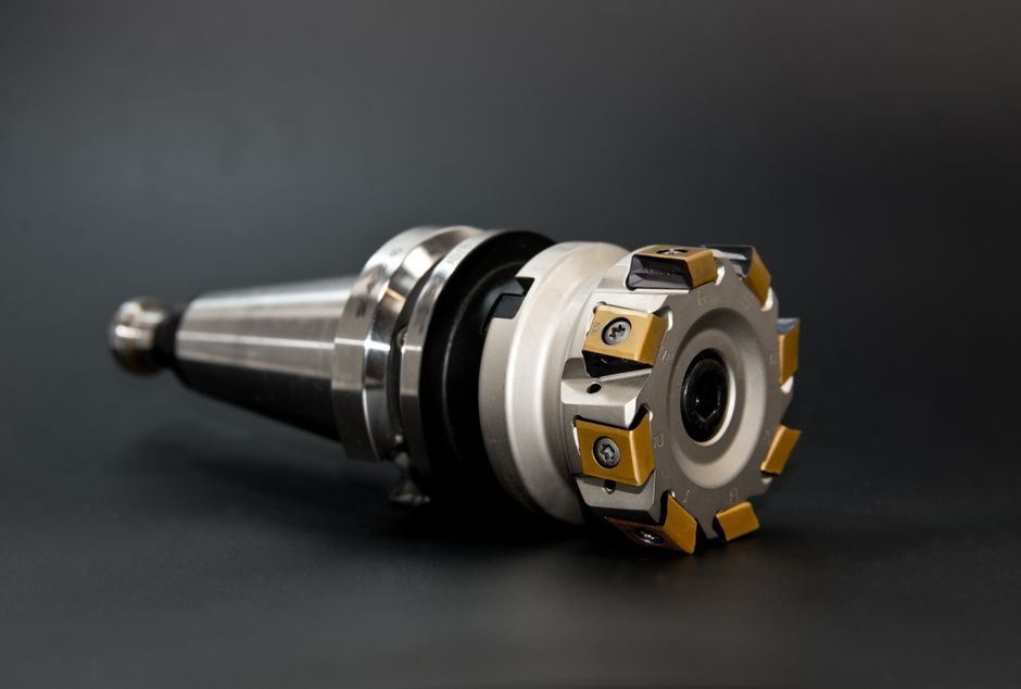
The Sumake ST-4250 pneumatic impact drill delivers 1,000 RPM free speed with a 16 mm (5/8") drilling capacity in steel, weighs 6.3 kg, and consumes 708 L/min (25 cfm) of compressed air at a 3/8" PT inlet — values that drive every hose, regulator and lubrication decision on the line [S1].
Specifying the wrong air supply or skipping oiler setup drops the impact mechanism's life by half and turns the 5/8" capacity rating into a 10 mm rating in practice. This guide walks through the install sequence for any facility receiving the ST-4250, or a comparable side-exhaust gear-type air reversible drill, and is structured so a maintenance engineer can hand it to an operator on first commissioning [S1].
Pre-Install Air Supply: Pressure, Flow and Filtration
The ST-4250 spec sheet lists air consumption of 25 cfm (708 L/min) and a 3/8" PT air inlet, with a recommended 3/8" ID air hose — meaning the upstream FRL (filter-regulator-lubricator) train must be sized for at least 25 cfm continuous flow at 6.2 bar (90 psi) operating pressure to keep tool RPM near the rated 1,000 [S1].
A 3/8" hose at 3 m or less keeps pressure drop under 0.3 bar; runs longer than 8 m should step up to 1/2" ID to hold tool performance. A 5 micron particulate filter plus a coalescing filter upstream of the regulator prevents water and rust from entering the impact mechanism, which is critical for gear-type drills running at the 6,283.2 rad/min tip speed [S1]. Mount the lubricator as close to the tool as practical — within 2 m — to keep the vane motor and impact mechanism oil-misted continuously.
Side-Exhaust Routing and Noise Control
The ST-4250 is a side-exhaust configuration, so exhaust air — and the oil mist carried in it — blows horizontally from the housing at roughly the operator's forearm height; a 1/2" ID duct or capture hose is mandatory in any indoor cell to keep the work area below typical shop OSHA PELs for mineral oil mist [S1].
Redirecting exhaust away from the workpiece also keeps chips and cutting fluid from being blown back into the operator's face during vertical or overhead drilling. For cells with multiple drills, route each side-exhaust into a manifold tied to a low-pressure extraction fan; do not vent into the same line as the shop compressed-air supply intake. The drill's overall length of 420 mm (16.5") and 6.3 kg mass make it usable in tight jigs, but the side-exhaust port orientation must be confirmed before the drill is locked into a fixture [S1].
Chuck, Bit Selection and Drilling Capacity Limit
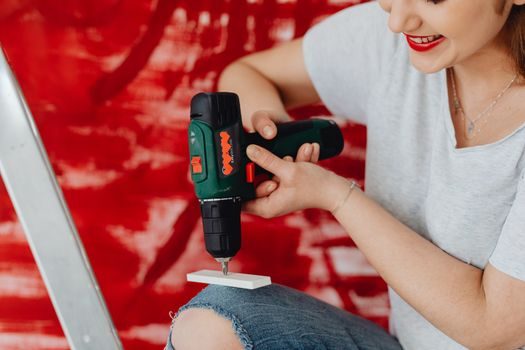
Drilling capacity is 16 mm (5/8") in mild steel — the spec's hard limit — and the gear-type mechanism means continuous-feed pressure above the rated load will stall the hammer, not break the bit; operators should treat 14 mm as the practical ceiling for production runs to leave margin on the impact stroke [S1].
Use only impact-rated jobber or shortened drill bits; standard HSS bits chip under the cyclic loading. For holes above 13 mm, peck-cycle every 5 mm of depth and withdraw fully to clear chips, because the side-exhaust does not pull swarf out of a deep hole. If the application is structural steel, confirm the workpiece is firmly clamped — the 6.3 kg mass plus impact reaction will torque a 16 mm bit hard enough to twist a free plate.
Reverse, Throttle and Ergonomic Handling
The ST-4250 is described as a 5/8" AIR REVERSIBLE DRILL (SIDE EXHAUST)(GEAR TYPE) — reversible by lever, not by valve swap — so the throttle handle must be locked-out when changing direction, and the bit must be at a complete stop before flipping the reverser to avoid chipping the gears [S1].
The "heavy duty type with small body" is qualified for hand-held operation, but the 6.3 kg net weight plus the 420 mm length produces non-trivial reaction torque on stalls; always drill with two hands and use a torque-absorbing glove. The "suitable for human body" wording on the data sheet refers to the body's geometric envelope, not to vibration exposure — for shift-long work above 3 hours, monitor HAVs (hand-arm vibration) per ISO 5349 and rotate operators [S1].
Lubrication Schedule and First-90-Day Checks
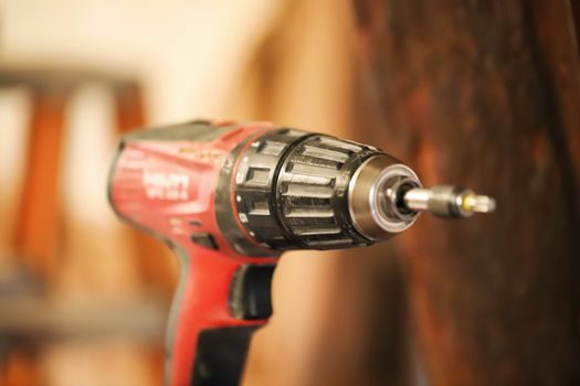
Pneumatic impact drills with gear-type mechanisms run hot — vane and gear wear accelerate above 50°C — so the inline lubricator should feed 2-3 drops per minute of light pneumatic tool oil (ISO VG 32) into the 3/8" PT inlet; the side-exhaust will visibly carry oil mist when the rate is right [S1].
At 100 hours, drop the air inlet screen and inspect for varnish; varnish means the lubricator ran dry. At 500 hours, the impact mechanism and gear pack should be regreased with the manufacturer's grease spec; do not mix lithium-complex and polyurea greases — they react and harden. Air consumption climbing above 25 cfm at no-load is the first indicator of vane or seal wear, and the tool should be pulled for service before the next production run [S1].
Comparison: Pneumatic vs Corded vs Cordless Impact Drills
On the four criteria that matter for a 16 mm steel drilling station — sustained power, shift runtime, ergonomics, and site safety — the pneumatic ST-4250 beats both corded and cordless impact drills on duty cycle and explosion-proofing, but loses on portability and noise [S1].
Air impact drills like the ST-4250 deliver constant torque for the full 8-hour shift because the compressor is the energy source, while cordless impact drivers derate after the 3rd or 4th deep hole as the battery sags. For ATEX-classified zones, pneumatic tools eliminate the spark risk that corded electric drills introduce. The trade-off is the 6.3 kg mass plus the 3/8" air hose tether, which is why pneumatic drills are usually paired with overhead balancers or linear guide-mounted drill slides in fixture cells rather than hand-held for long runs [S1]. For a general comparison against pistol-grip nut-runners in the same air-tool family, see the air impact wrench reference page.
Installation Acceptance Checklist

Before sign-off, verify free speed under load reaches the rated 1,000 RPM at 6.2 bar with a tached drill; any reading below 900 RPM points to undersized hose, kinked supply, or a starving compressor, not a faulty tool [S1].
Confirm the lubricator is feeding (oil visible at exhaust), the side-exhaust is captured, the reverser is butter-smooth in both directions, and the chuck runs true within 0.05 mm at the spindle. Log baseline vibration at the operator's hand position and the no-load air consumption (it should sit within ±5% of 25 cfm); these two numbers form the trend baseline for the first 90 days. For new cells planning a fixed drill head, see the urethane casting selection guide on fixture material choices, or the mesh belt conveyor installation guide if the drill is part of an in-line transfer line.
Trackable signals to watch over the next 6 months: any vendor update to the ST-4250 spec sheet (Sumake's product page lists a sibling ST-4250-6 variant, so a similar revision to the base model would be the first place to look for design changes) and any field bulletin on vane or impact-mechanism service kits.