
A robotic workcell power monitoring system is treated by most integrators as a three-layer stack: a revenue-grade energy meter on the 400-480 V AC feed, a condition monitoring system on each servo drive and DC bus, and a supervisory logging node that records kWh, voltage sags, and harmonic distortion to a time-stamped database [S3].
The certification question is which clauses of which standards apply to which box. A watt-hour meter at the workcell cabinet landing, a clamp-on power meter on a 24 V DC robot control bus, and a partial-discharge sensor on a 6 kV feed all fall under different evidence rules, and a checklist must keep them separate rather than lumping them under one generic "power monitor" label [S1][S2].
Layer 1: Cabinet-Landing Revenue Meter, and Why Class Matters
The cabinet-landing meter in a robotic workcell is almost always a three-phase four-quadrant unit rated for 50/60 Hz, 400 V L-L nominal, with Class 1 active energy accuracy under IEC 62053-21 or its ANSI C12.20 equivalent at 1.0 accuracy class, because the same point is used both for internal sub-billing and for proof of consumption during ISO 50001 energy reviews [S1].
Audit evidence required at this layer is: the meter nameplate bearing the accuracy class and the certifying body mark, a current calibration certificate dated within 12 months, the CT ratio and burden stamped on the wiring diagram, and a one-page test record showing ±1 % error at 5 % of nominal current, at unity power factor, and at 0.5 lagging. Skipping the lagging-power-factor point is the single most common finding, because servo drives draw a current with a phase angle that drifts well below 0.9 during regen events [S2].
Layer 2: DC Bus and Drive-Branch Monitoring
Inside the workcell, the 24 V DC robot controller rail, the 48-96 V DC servo bus, and any 200 V DC drive link are measured by branch monitors with a working DC range that covers the regen overshoot, not just the nominal. A typical 50 kW WattsVIEW-class unit publishes a 0-200 V DC voltage range with a -75 to +105 A current window for one model and a -180 to +250 A window for the higher-current variant, with measurements including DC V, A, W, Wh, Ah and calorie equivalents, which is enough resolution to spot a 2 % drift on a drive link before it trips the safety circuit [S2].
The certification evidence for this layer is a functional test record showing four-quadrant operation (motoring and regen), not just forward power. Auditors reject monitors that read zero or clamp when the drive is regenerating into the bus, because a robotic workcell running frequent decel ramps will spend 10-30 % of cycle time in regen, and a meter that hides that energy defeats the whole monitoring intent. The branch monitor also needs a logged timestamp and either Modbus TCP, RS-485 Modbus RTU, or a documented API so the supervisory node can pull the value at the same cadence as the energy meter [S2].
Layer 3: Power Quality and Sag Detection
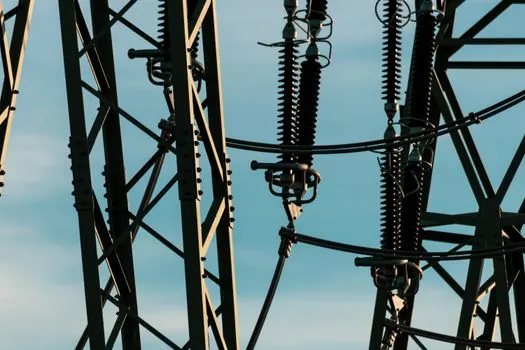
A robotic workcell is sensitive to voltage sags as short as 4-8 cycles on the 400 V bus, because a 6-axis robot mid-path will fault out and lose its taught position if the servo bus drops below roughly 85 % nominal for more than half a cycle. The power monitoring system at this layer is therefore not a kWh meter, it is a power quality instrument with sag, swell, and harmonic recording to IEC 61000-4-30 Class A or Class S, and the certificate asked for is the manufacturer's test report demonstrating the chosen class on each measurement channel [S3].
Common audit failures here: a Class S meter being claimed as Class A, a missing THD channel on the neutral conductor, and a sag log without a corresponding RMS timestamp at 1-cycle resolution. The corrective action is to specify the class by name on the BOM, not just "power quality meter", and to keep the manufacturer's declaration of conformance in the same folder as the calibration certificate [S3].
Side-by-Side Comparison of the Three Layers
The three layers look similar in a one-line BOM but are not interchangeable. The cabinet-landing energy meter is for billing and ISO 50001 evidence, governed by IEC 62053-21 Class 1, with annual calibration; the drive-branch DC monitor is for process energy visibility, governed by the supplier's published DC accuracy and four-quadrant test record, with no third-party accuracy class; the power quality instrument is for sag and harmonic evidence under IEC 61000-4-30 Class A or S, with a manufacturer declaration that names the class. A checklist that asks for one certificate to cover all three is a known audit defect, and a corrective action is to split the evidence folder by layer, not merge it [S1][S2][S3].
Wiring, CT Selection, and Witness Test
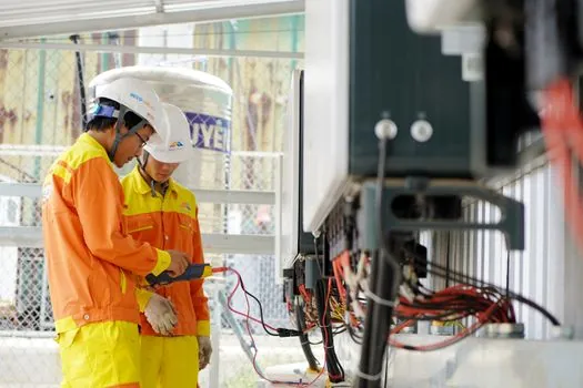
Current transformer selection is the practical link between the three layers. For the cabinet landing, a solid-core or split-core CT with a stated burden of at least 0.5 VA at the chosen ratio (for example 200:5 or 400:5) prevents ratio error at low current, and the meter's nominal burden must be at or below the CT's stated value, not above it. For drive branches, Hall-effect or shunt-based DC transducers are used because CTs do not pass DC, and the transducer's response time must be under 100 ms to catch regen events on a 200 ms decel ramp [S2].
The witness test is a one-hour procedure that records three datasets: 60 minutes of normal cycle showing kWh accumulation in both directions, a 10-cycle sag event captured by the power quality layer, and a 1-minute no-load baseline that should read within the meter's published no-load threshold. The witness test report, signed by the integrator and the end-user electrical engineer, is the document an ISO 50001 surveillance auditor will request first, ahead of any certificate, because it proves the system was verified as installed rather than only as designed [S3].
Documentation Folder an Auditor Actually Opens
The documentation folder that survives an audit has a fixed structure: a one-page single-line diagram showing the meter, CT, and transducer locations, the meter nameplate photos, the calibration certificates with traceability to a national lab, the manufacturer's IEC 61000-4-30 conformance letter with the class named, the witness test report, and the data dictionary that maps each Modbus register or API field to a kWh, kVArh, or sag event. Any item missing from that sequence triggers a finding on the spot [S3].
Two trackable signals confirm the checklist is being followed: a falling count of "meter type unspecified" line items on integration purchase orders, and a rising share of retrofits where the Layer 2 DC branch monitor and the Layer 3 power quality instrument are quoted on the same line item as the cabinet-landing meter, indicating the integrator is treating the workcell as one measurement scope rather than three independent purchases [S1][S2]. See how that scope is approached on a comparable industrial assembly setup in this stacker crane spec walkthrough for e-commerce fulfillment, where the same three-layer measurement logic is used on the drive side.
Spec-level background on the components involved: vibration condition monitoring.