A pressure pour holding furnace with a channel inductor stores, superheats, and gravity-pressurized-doses molten cast iron into the molding line from a sealed vessel blanketed with air or inert gas, with the inductor fitted to the bottom or side of the bath [S1][S3]. On a typical cast-iron line, melting the charge at about 1450 °C draws 510 to 550 kWh/t, and the subsequent holding, handling, and pouring cycle adds another 150 to 230 kWh/t, so holding equipment is a non-trivial slice of the total energy bill [S4].
The upstream melter is decoupled from the molding line by a sealed holding vessel, and the inductor is the only active heating element, so the bath stays at the pouring setpoint while the molding line cycles at its own cadence. That decoupling is the operational reason channel-inductor pressure pour units sit between cupola or coreless induction melters and automated pouring stations on most high-output iron lines [S1][S4][S5].
How a Pressure Pour Channel Unit Is Built and Run
A pressure pour channel furnace is a sealed holding/pouring vessel blanketed with an inert gas or air atmosphere, with an inductor attached to the bottom or side of the bath and metal discharged through a stopper-rod nozzle or a similar unheated pouring device [S3][S4][S5]. The closed vessel prevents gas absorption, and inductive heating eliminates the metal loss that would otherwise come from a combustion-fired holding lid, which is why foundries chasing low-inclusion ductile iron gravitate to this arrangement [S1].
Operationally, the unit does three things at once: it acts as a thermal buffer between the melter and the molding line, it serves as an energy accumulator by absorbing off-peak power through a downstream charging melter, and it enforces homogeneous bath temperature ahead of the pour [S1]. Holding furnace vessels in this class are typically sized to store enough liquid iron to ride out short melter outages and feed several hours of pouring without a melter restart.
Channel Inductor Geometry: Vertical vs Horizontal
Vertical-channel inductor designs, exemplified by the FOMET Dupour PR-V, are specified for automatic pressure pouring of grey and ductile iron where the inductor sits below or beside the bath and supports both holding, superheating, and direct pouring of any type of cast iron [S7]. Horizontal-channel inductor builds, by contrast, are most common in classic vertical-shaft holding vessels where the channel is wrapped around the lower shell of a cylindrical bath and the loop is essentially an external heat exchanger for the metal [S1][S2].
For foundries pouring large or continuous castings, vertical-channel geometries are the practical way to handle big metal volumes, with the channel furnace acting as a holding unit ahead of the molding plant that delivers metal through an unheated pouring device on a stopper-rod [S2][S4][S5]. The choice between the two is driven less by efficiency and more by vessel footprint, refractory access for relining, and how the foundry services the inductor loop when it eventually fills with buildup.
Refractory Liner Practice: Dry-Vibrated Channel Lining
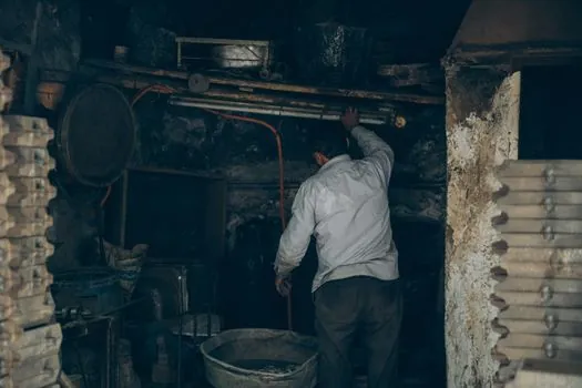
The dominant liner build for channel inductors in iron foundries is the dry-vibrated lining technique, with the dry lining process first developed for holding-furnace channel inductors and subsequently carried over to automatic casting and press-pour units [S6]. For the upper vessel, a highly insulated alumina-silica or magnesia-based refractory is dry-vibrated around a steel former and then sintered against the bath on first heat-up, which gives a tight, slag-resistant working lining.
Lining life in channel inductors is governed by slag chemistry, not by raw temperature: when slag makes contact with a refractory wall that is colder than the slag melting point, it freezes onto the wall as buildup, and high-melting-point slags are especially prone to promoting this growth [S3]. Frequent additions of specific fluxes are used in channel furnace operation to keep emulsified oxides and sulfides from nucleating on the channel throat, with the practical effect that refractory service life tracks the foundry's deslagging discipline more than any other variable [S3].
Buildup, Slag, and Operating Discipline
Slag formation in iron melting is inevitable, and the cleanliness of the metallic charge, often sand-encrusted gates and risers or rust- and dirt-encrusted scrap, drives the type of slag formed during the melt cycle [S3]. In an induction bath, magnetic stirring keeps non-metallics in suspension as an emulsion; once the particles grow large enough that buoyancy overcomes stirring, they float and coalesce as a removable slag layer, and only then can they be skimmed off rather than re-deposited in the channel [S3].
Buildup is a classical nucleation and growth process: once a thin solid film of slag precipitates on a refractory surface, additional liquid slag nucleates on the already-solidified film because the surface is crystallographically similar, and the layer thickens fast [S3]. Failure to flux or remove emulsified phases during the holding cycle reduces overall metal-handling efficiency long before the bath temperature drifts, which is why channel furnace operators treat the inductor as a slag-management component, not just a heater.
Process Economics, Molding-Line Disruptions, and Defect Rates

More than 10 percent of all molding line disruptions trace back to a lack of pourable metal at the right temperature, and roughly one-third of all molding defects are attributed to flaws in the melting and pouring process rather than to the molding equipment itself [S4]. Holding and pouring cycle energy at 150 to 230 kWh/t is on top of the 510 to 550 kWh/t needed to melt cast iron charge at 1450 °C, so any improvement in the holding step directly improves the line's kWh-per-tonne benchmark [S4].
That economic profile is what justifies the capital cost of a sealed pressure pour unit over an open ladle pour: the unit pays back by smoothing out the melter/line interface, allowing off-peak charging of the upstream melter, and trimming the holding-plus-pouring energy slice of the bill. For a high-mix plant evaluating whether to upgrade from a ladle-and-stopper pour to a pressurized channel holding furnace, the calculation comes down to disruption cost per shift and energy per tonne, both of which the holding furnace attacks directly.
Sourcing Standards and Vendor Landscape
Channel inductor pressure pour units for cast iron are commonly sourced from a handful of established induction furnace builders: OTTO JUNKER lists channel type holding furnaces as a standard product family for iron foundries and has published the energy and process figures that have become de facto reference values for the technology [S1][S4]. Ajax TOCCO markets vertical-channel induction melting and holding furnaces sized for large or continuous casting, which describes the same equipment class configured for high-throughput iron lines [S2]. FOMET's Dupour PR-V is the named reference for a vertical-inductor pressure pour unit on grey and ductile iron [S7].
Foundry engineers specifying a unit for a new molding line or a brownfield replacement should request three pieces of data from any bidder: the kWh/t figure for the holding-plus-pouring cycle at the rated throughput, the channel inductor relining interval in campaigns or months under the buyer's slag regime, and the maximum pouring temperature for ductile iron with the documented atmosphere control, since all three numbers determine the lifecycle cost more than the nameplate kW rating. For broader context on how iron foundries organize the upstream melt, the cast iron material reference and the molding process entry are useful cross-checks when scoping a new line. Trackable signals for the next planning cycle: published relining intervals and energy benchmarks from the three vendors named above [S1][S2][S7], and any foundry-side data on whether vertical-inductor pressure pour units are displacing horizontal-channel holding vessels on new ductile iron molding lines.
See also our earlier report, OSSD to Safety PLC: 2026 Wiring Rules for Light Curtains.