
Spring-loaded pressure relief valves dominate process-industry specifications because they handle a wide set-pressure range, tolerate moderate backpressure when balanced-bellows designs are used, and are accepted under ASME BPVC Section VIII for unfired pressure vessels [S1]. Weight-loaded and pilot-operated variants address the cases spring units handle poorly: large orifice area on low-pressure tanks, and tight set-pressure tolerance on high-capacity services [S1].
Selection is governed by the relief scenario, not the brand. Engineers must identify the design overpressure, the relieving duty (fire, blocked outlet, thermal expansion, control-valve failure), the required orifice area, the allowable accumulation, and the compatible material/wetted-parts trim before any vendor list is opened [S1][S8].
Valve Types and Where Each One Fits
Spring-loaded relief valves cover the bulk of process duty: set pressures from low psig into the thousands, with conventional, balanced-bellows, and bellows-sealed sub-variants chosen by backpressure and process toxicity [S1]. Weight-loaded (dead-weight) valves are typically used on low-pressure storage tanks and atmospheric receivers where set pressure is well below 15 psig and a simple gravity-loaded pallet is mechanically appropriate [S1].
Pilot-operated relief valves (PORVs) use a small pilot to sense pressure and a larger main disc to discharge flow; they are favored when a narrow 3% or 5% blowdown band is required, when set pressure is below about 50 psig but relieving capacity is large, or when inlet piping losses would otherwise starve a direct-acting spring unit [S1]. Vacuum-relief and emergency-pressure-relief hatches serve atmospheric and low-pressure storage where over- or under-pressure can buckle a tank shell during filling or thermal swing [S1].
Set Pressure, Accumulation, and the API 520/521 Logic
ASME BPVC Section VIII sets the legal floor: a relief valve on an unfired pressure vessel must be set at or below the maximum allowable working pressure (MAWP), and the vessel is permitted to accumulate above MAWP only by the percentage the code allows for the specific scenario — commonly 10% for fire exposure and 16% for an upset such as a blocked outlet, depending on the code edition and the marking used [S8]. API 520 Part I and API 520 Part II translate those code allowances into a sizing workflow: required orifice area is computed from the design case relieving load (lb/hr or SCFM), the fluid properties, the set pressure, and the allowable overpressure, then corrected for backpressure and capacity derating [S8].
API 521 then names the credible upsets that must be evaluated — fire, loss of cooling, blocked discharge, utility failure, control-valve failure modes — and forces each one into a separate case so the largest required orifice wins [S8]. Practical consequence: a vessel often needs one larger valve, not a stack of small ones, because two small valves with identical set pressure do not protect against the case where the larger single orifice is required to pass the fire-case load [S8].
Sizing Inputs That Drive the Orifice Letter
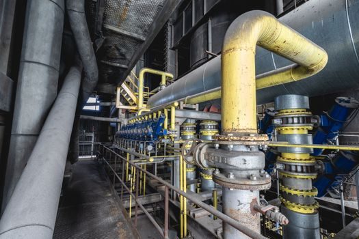
Orifice designation is the single number that controls capacity. The standard API 520 area designations run from D (smallest) through E, F, G, H, J, K, L, M, N, P, Q, R, and T, with rated discharge areas tied to the valve body geometry; choosing one letter is the result of the calculation, not the starting point [S8]. Three input numbers carry most of the risk: the set pressure, the required mass or volumetric relieving rate, and the backpressure at the valve outlet during discharge.
Backpressure is where selection typically fails in the field. A conventional spring valve loses lift and capacity as superimposed backpressure rises; a balanced-bellows design holds set pressure within tolerance up to roughly 50% of set pressure, with the exact envelope defined in the manufacturer's certified capacity curve [S1][S8]. Where reactive or variable backpressure exceeds that envelope, a pilot-operated valve with a supplementary diaphragm loading area is the engineered answer, because the pilot sees the actual downstream pressure and trims accordingly [S1].
Materials, Wetted Parts, and Process Compatibility
Wetted-parts selection is driven by the process fluid, not the line class. Carbon-steel bodies with stainless trim cover most hydrocarbon service; alloy bodies (Alloy 20, Monel, Hastelloy) are specified for sulfuric, hydrofluoric, or wet HCl exposure where carbon steel cannot be tolerated; and PTFE or graphite soft seats are used where tight shut-off below set pressure is required and the service temperature is within the soft-seat envelope [S1][S8].
NACE MR0175/ISO 15156 sour service restricts hardness of wetted parts and excludes some elastomers when H2S partial pressure exceeds defined thresholds; the metallurgical and NDE requirements must be ordered with the valve, not added later [S8]. Glove-box and instrument-air service uses small low-set-pressure units whose bodies are commonly brass or stainless and whose springs are sized for sub-psig-to-low-psig cracking pressure [S3].
Standards, Code Stamps, and Documentation Buyers Should Demand

Three document trails separate a spec-grade valve from a commodity one. First, the ASME UV stamp or equivalent national code stamp certifies the pressure-containing boundary; without it, the valve cannot be legally installed on a Section VIII vessel in most jurisdictions [S8]. Second, the manufacturer's capacity certificate ties the orifice area to a measured coefficient of discharge (typically Kd in the 0.85–0.95 range for sensible service when the valve is installed per API 520 Part II rules) and to the certified bench-test set pressure [S8].
Third, the material test report (MTR) and NACE compliance certificate (where applicable) close the metallurgical loop. Bypassing any one of these is the most common audit finding when an incident is reviewed [S8]. For flare-header interfaces, API 521 also requires the engineer to confirm that the relief path is routed to a safe location and that the inlet pressure drop from the protected equipment to the valve does not exceed 3% of set pressure for non-fire cases [S8].
Common Selection Errors and the Limits of "Off-the-Shelf" Sizing
Four mistakes account for most misapplied valves. (1) Sizing only the normal-operating case and missing the fire case, which can be 5–10× the normal vapor load on an insulated vessel [S8]. (2) Treating two small valves as a substitute for one large valve, which fails the single-largest-load case logic of API 521 [S8]. (3) Ignoring inlet piping loss between the vessel and the valve, which starves the valve and the pressure gauge reading used to verify set pressure [S8]. (4) Specifying a conventional spring valve where backpressure exceeds the manufacturer's limit, when a balanced-bellows or pilot-operated variant is required [S1].
Where service is non-process — compressed-air receivers, hydraulic accumulators, low-pressure oil reservoirs — a safety relief valve with a National Board or CE/PED marking is usually the right fit, and an OEM-published flow curve replaces a full API 520 calculation [S1]. For mobile and engine service (diesel common-rail limiters, hydraulic circuit protection on construction equipment), a cartridge-style pressure relief valve set to the system's working pressure is the standard reference, with the relief crack pressure usually held within ±5% of the working pressure target [S5].
Shortlist Logic and What a Spec Should Look Like
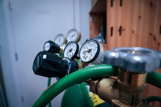
A defensible shortlist filters on five hard criteria, in this order: set pressure and code-stamp envelope, required orifice area from the API 520 calculation, backpressure tolerance (conventional / balanced-bellows / pilot-operated), wetted-parts material against the process fluid, and documentation package (UV stamp, capacity cert, MTR, NACE) [S1][S8]. A spec that omits any one of the five should be returned for revision before the vendor is contacted.
For downstream isolation after the relief valve, a swing check valve selection review should run in parallel so the backpressure envelope and the discharge line class are consistent; the same logic applies to upstream strainers covered in a basket strainer selection review, since a clogged inlet screen will silently disable a relief device. Two trackable signals to watch: any facility-level change in set pressure or accumulation percentage that flows through an MOC review, and any 2026 release of API 520/521 errata or supplement that shifts the sizing workflow; both should be re-validated against the in-house relief device inventory before the next turnaround.
Spec-level background on the components involved: linear guide.