
In a 4-20mA pressure transmitter, the 4 mA and 20 mA points are not fixed engineering values: they are the lower and upper range limits (LRV and URV) that the technician configures into the device, and every pressure in between is converted to a proportional current using the formula mA = 4 + 16 × (Reading − LRV) / (URV − LRV) [S4]. On a sensor ranged 0 to 100 psi, that produces 0 psi → 4 mA, 25 psi → 8 mA, 50 psi → 12 mA, 75 psi → 16 mA, and 100 psi → 20 mA [S3].
The 4 mA offset is intentional: a true process zero is signaled by a non-zero current (4 mA), and a broken wire or failed sensor falls to 0 mA, so the receiving PLC, DCS, or pressure gauge indicator can flag the failure instead of misreading it as a real zero [S1][S3]. This is the live-zero property that has kept 4-20mA dominant in oil and gas, water treatment, pharmaceutical, and general process plants for decades [S1].
The transfer formula and a worked example
The 4-20mA transfer is linear between LRV and URV, and a 100 psi range at 50 psi input yields (50/100) × 16 + 4 = 12 mA exactly [S5]. The same math on a 0 to 10 bar range gives 0 bar → 4 mA, 2.5 bar → 8 mA, 5 bar → 12 mA, 7.5 bar → 16 mA, and 10 bar → 20 mA, which is the standard 25%/50%/75% scale the receiving system uses to back-calculate the process variable [S3].
Two conventions matter. First, the percentage is of span, not of absolute pressure: 12 mA is 50% of a 0-100 psi range regardless of whether the medium is gauge, absolute, or differential. Second, the range can be turned upside down for inverted applications: a 20 to 4 mA span is built by swapping LRV and URV in the same formula [S4]. The Sensors One tool accepts psi, bar, kPa, inH2O, and other units interchangeably, and it also exposes a 0-20 mA, 0-10 V, 0-5 V, 1-5 V, 0.5-4.5 V, and mV/V variant for non-current outputs [S4].
Why the 4 mA floor exists, and what each current level really means
The 4-20mA standard uses 4 mA as the "live zero," which lets the controller distinguish a true zero process measurement from a 0 mA loop failure, and it also lets the loop power the transmitter off the same two wires that carry the signal [S1][S3]. In a two-wire loop, the same pair of conductors carries DC power into the device and the 4-20 mA signal back out, so installation is typically just a power supply, the transmitter, and a sense resistor at the receiver [S1].
Inside the loop, typical faults decode to specific currents. Around 4 mA: real process zero, or sensor at LRV, or open element on a one-sided gauge. Around 12 mA: half-span. Around 20 mA: sensor at URV, or a saturated over-range. Below 3.6 mA or above 21 mA on a NAMUR NE43-compliant device, the reading is out of the valid signal range and should be treated as a diagnostic fault, not a process value [S3]. That NE43 band is the de-facto alarm window, and modern PLC analog input cards are usually configured to flag < 3.6 mA and > 21 mA as bad-quality data. A typical hobby or bench interface uses a 250 Ω sense resistor with a 5 V ADC reference, or 51 Ω with the 1.1 V internal reference, to convert the current back into a voltage the microcontroller can read [S2].
Wiring topology, sense resistor sizing, and ADC interface
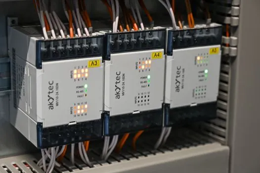
Most industrial pressure transmitters are two-wire loop-powered devices, so the same pair of wires that powers the unit also carries the 4-20 mA signal, which is one of the reasons 4-20 mA is preferred over 0-5 V or 0-10 V for long cable runs: voltage drops on long wires do not affect the current, only the loop compliance [S1][S3]. For a 24 V DC supply and a 250 Ω load, the loop sees 24 V − (20 mA × 250 Ω) = 19 V across the transmitter, which is well within the typical 12-30 V compliance of a modern industrial transmitter [S1].
On a 5 V Arduino ADC, the standard practice is a 250 Ω resistor to convert 4-20 mA into 1-5 V, which maps cleanly to the 0-1023 ADC range with about 4.88 mV per count, and a common failure mode in hobby builds is a floating converter ground that produces random 0-1023 readings, which is fixed by bonding the converter GND to the Arduino GND at one point only [S2]. For low-voltage ADC references, a 51 Ω resistor with the 1.1 V internal reference produces about 0.2-1.0 V across the sense element and avoids the 5 V rail noise of USB-powered boards [S2].
Selection criteria: when 4-20mA is the right output, and when it is not
4-20mA is the right output when the run is long (over 50 m to a motor control center or remote wellhead), the environment is electrically noisy (VFDs, switchgear, large motors), the device is loop-powered from a 24 V DC rail, and the receiving system is a PLC, DCS, SCADA RTU, or dedicated pressure sensor indicator that accepts analog inputs natively [S1][S3]. It is also the right call when the safety system needs a hardware-level broken-wire fault: a 0 mA reading is unambiguously a failure, and that single property is why 4-20mA persists in SIL-rated loops and burner management systems [S1].
For purely local readouts, a 0-5 V, 0-10 V, or 0.5-4.5 V ratiometric output avoids the 4 mA floor entirely, and ratiometric 0.5-4.5 V outputs are common on 5 V-powered MEMS pressure sensors because they track the supply and reject the excitation error that absolute-voltage outputs carry [S4].
Comparison of 4-20mA against the common alternatives
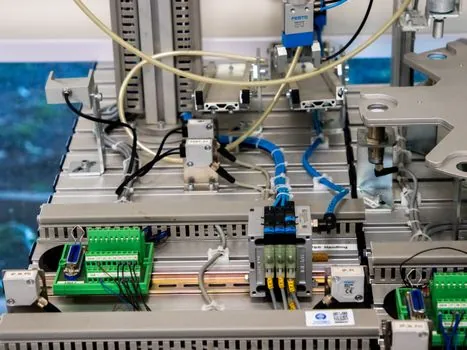
Against the realistic alternatives, the decision is dominated by four criteria: noise immunity, broken-wire detection, power delivery to the field device, and compatibility with the existing input card. 4-20mA wins on the first three: current is not affected by wire resistance or induced noise on long runs, the 4 mA live zero gives a free broken-wire diagnostic, and the same two wires carry loop power [S1][S3]. 0-10 V is cheaper at the device and easier to read on a bench, but it has no broken-wire diagnostic, it is vulnerable to voltage drop on cables longer than about 5-10 m, and it cannot power the sensor from the signal pair [S3]. HART keeps the 4-20mA analog layer and overlays a 1200 bps FSK signal for digital configuration, two-point calibration, and remote diagnostics, so it is the right upgrade path when the analog card is already in place but digital data is needed. A ratiometric 0.5-4.5 V output is the right call on 5 V MEMS modules where power budget is tight and the cable is short. In a pressure calibrator shop, the same sensor family is often available in all five variants so the same diaphragm can be specified into a loop-powered skid or a 5 V OEM board without redesign [S4].
Failure modes, common pitfalls, and verification steps
Three failure modes account for most field service calls. First, a multi-drop wiring error where the shield is grounded at both ends, which creates a 50/60 Hz ground loop that rides on top of the 4-20 mA signal and shows up as 0.5-2 mA of jitter on the receiver. The fix is to ground the shield at one end only, typically at the panel, and to use twisted pair throughout. Second, a loop-power polarity reversal on a two-wire device, which simply gives 0 mA, but on a four-wire device it can damage the output stage. Third, a sense resistor mismatch on a panel meter that is calibrated for 250 Ω when the installed resistor is 51 Ω, which compresses the displayed range by a factor of about five [S2].
Verification is straightforward. Disconnect the loop at the transmitter, inject a precision 4.000 mA, 12.000 mA, and 20.000 mA source from a calibrator, and confirm the receiver reads 0%, 50%, and 100% of span. Then reattach the loop, apply a known pressure at 0%, 25%, 50%, 75%, and 100% of span with a dead-weight tester or a pressure transmitter calibrator, and confirm the receiver matches the calculation mA = 4 + 16 × (Reading − LRV) / (URV − LRV) to within the stated accuracy, typically ±0.1% to ±0.25% of span for industrial-grade units and ±0.05% for high-accuracy units [S3][S4][S5]. On a 0-100 psi sensor at 50 psi, the expected value is 12 mA; anything outside about ±0.04 mA on a 0.1% device is a candidate for re-zero or re-span on a five-point up-and-down test [S5].
Trackable signals: a NAMUR NE43 diagnostic trip below 3.6 mA or above 21 mA on a specific loop, an open shield ground at one end of the run, and a five-point calibration certificate that records the as-found versus as-left mA at 0/25/50/75/100% of span, all of which are concrete checks that can be repeated on the next outage.
Background reading: Mini Concrete Mixer Truck 2-4 m³: Dimensions, Chassis Fit, Site Limits.