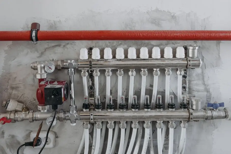
The single most common selection mistake in 2026 is buying a transmitter with too wide a range, then spending the next decade reading 8 to 12 bar on a 0 to 50 bar cell. A widely used rule of thumb in the field is to size the upper range value at roughly 1.5 times the expected maximum process pressure, including spikes and startup transients [S1].
For hazardous service, the same rule gets a second constraint: normal operation should sit between 30 and 80 percent of the calibrated span, because running near full span leaves no headroom for upsets [S4]. On top of that, area classification, gas group, and temperature class (T1 to T6) decide which protection concept the device must carry, which is a separate decision from range and accuracy [S4].
Set the three numbers before you open a catalog
Before comparing brands, write down the minimum operating pressure, the normal operating pressure, and the maximum operating pressure including transients [S1]. A process that runs at 20 bar with occasional spikes to 28 bar is served by a 0 to 40 bar cell, not a 0 to 100 bar cell, because percentage-of-full-scale error inflates as you move away from the calibrated midpoint [S1].
For a pressure transmitter used as a differential pressure transmitter on flow, level, or filter service, the same range logic applies but the upper end must also exceed the static line pressure on both sides of the primary element [S2]. A square-root extraction is normally applied for orifice, Pitot, or Venturi primary elements, so usable turndown matters more than nominal range [S2].
Match the output signal to the receiving card first
Three outputs dominate the 2026 market: 4 to 20 mA current loop, 0 to 10 V or 1 to 5 V voltage, and digital fieldbus protocols such as HART, Modbus, or Foundation Fieldbus [S1]. The 4 to 20 mA loop is the default because it is noise-resistant over long cable runs and is the easiest input to wire into any PLC or DCS analog input card [S1].
Voltage outputs (0 to 10 V or 1 to 5 V) are common in HVAC and building automation where cable runs stay short, but they tolerate less electrical noise than a current loop [S1]. Digital protocols are preferred in larger or more instrumented systems where remote diagnostics and multidrop wiring pay for themselves; a HART signal is overlaid on a 4 to 20 mA loop, while Foundation Fieldbus and PROFIBUS PA replace the analog current with a fully digital segment [S1]. Confirming the analog input card specification before ordering is the single most common reason returned transmitters are returned [S1].
Pick wetted materials and sensing technology for the media
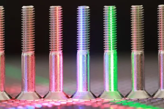
Piezoresistive silicon diaphragms are the most widely deployed sensing element in industrial process control, with accuracy between 0.1 percent and 0.25 percent of full scale and a primary failure mode of temperature-induced zero drift of roughly 0.02 to 0.05 percent per degree C above baseline [S5]. Capacitive sensors reach 0.04 to 0.1 percent of full scale and are the preferred choice for custody transfer and regulatory metering because of extremely low long-term drift [S5].
Strain gauge sensors in a Wheatstone bridge configuration deliver 0.3 to 1.0 percent of full scale accuracy and survive in high-pressure and high-temperature environments where silicon-based sensors would fail, which is why they remain common in hydraulic press, boiler, and compressor monitoring [S5]. For OEM machinery, flush-diaphragm and sanitary connections are specified where cleanability matters more than raw accuracy, while submersible and hydrostatic level probes are chosen for tank level rather than inline pressure [S3]. Wetted-parts compatibility with the process media is frequently more important to long-term ROI than the headline accuracy number [S2].
Compare the four main transmitter types against decision criteria
Gauge, absolute pressure transmitter, differential, and sealed gauge cover roughly 90 percent of industrial duty; the table below lines them up against the criteria that actually drive a purchase order. [S3]
Gauge transmitters reference atmosphere, cost the least, and fit hydraulic, pneumatic, and pump skids where the process is vented to the local air column [S3]. Absolute units reference a sealed vacuum and are required for any measurement that must be independent of barometric change, including tank level on a closed vessel and most flow mass calculations [S3].
Differential pressure transmitters are the workhorse for flow, level, and filter monitoring and require static-pressure ratings well above the measured differential, with square-root extraction for orifice-type flow elements [S2]. Sealed gauge units are the right call when the process media is incompatible with a vented reference and the absolute reference is not required, such as in many refrigeration and compressor packages [S3]. A 4 to 20 mA plus HART output covers the widest range of receiving systems and remains the safest default in mixed-vendor plants [S1].
Hazardous-area specification: classification, gas group, and protection concept
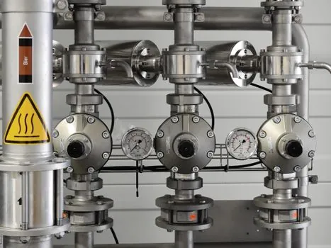
Area classification is the first number to set, not the last. Zone 0 means a flammable atmosphere is present continuously, Zone 1 means it is likely during normal operation, and Zone 2 means it appears only under abnormal conditions, with North American Class/Division systems placing Zone 0 and Zone 1 into a single Division 1 [S4].
Gas group defines the substance: Group IIA covers propane-type materials, Group IIB covers ethylene, and Group IIC covers hydrogen and acetylene with the strictest design requirements because those gases ignite at lower ignition energy [S4]. Temperature class T1 to T6 sets the maximum surface temperature the device may reach, and that figure must stay below the auto-ignition point of the substance present [S4].
Protection concept is selected to match the zone. Intrinsic safety (Ex ia or Ex ib) limits electrical and thermal energy below ignition thresholds and requires a barrier or galvanic isolator in the safe area, while explosion-proof construction (Ex d) contains ignition inside a robust housing with threaded flame paths and conduit seals [S4]. Non-incendive (Ex nA) suits Zone 2 or Division 2 only, where a flammable atmosphere is not expected during normal operation [S4]. The IEC 60079 series is the defining standard for equipment in explosive atmospheres; ATEX covers Europe, IECEx is the international scheme, FM certifies in North America, CSA covers Canada, and UKCA applies in Great Britain, and these marks are not interchangeable for a multi-site spec [S4]. For Safety Instrumented Function (SIS) loops, SIL capability, redundancy architecture, and proof-test interval must be defined at project start, because retrofitting them later is the most expensive way to fix a transmitter spec [S4].
Who should not pick the cheap gauge transmitter
A general-purpose gauge cell is the wrong pick when the media is corrosive, when the process is a closed vessel where atmospheric reference is meaningless, or when the measurement feeds a custody transfer or a safety trip [S2]. A 0 to 50 bar gauge unit on a 20 bar process is also a bad call, even on a benign medium, because the operating point sits in the noisy bottom of the calibrated span [S1].
Plants that are standardising on HART or Foundation Fieldbus should avoid a pure analog-only transmitter that lacks the device descriptor, because they will pay for it later in commissioning and predictive-maintenance tooling [S2]. Submersible level probes are not a substitute for inline gauge or absolute units on pump discharge or compressor interstage monitoring [S3]. For a deeper dive on output protocol trade-offs and reference style, the pressure sensor sizing and selection guide covers the same range-versus-output decision tree in more depth.
Shortlist logic and signals to track

A defensible shortlist in 2026 is built by locking the three process numbers first, then eliminating any cell whose upper range value is more than 2x the expected maximum or whose normal operating point falls outside 30 to 80 percent of span [S1][S4]. Candidates should be filtered to those with wetted materials certified for the process media, the correct area classification and gas group, and an output protocol the receiving card actually accepts [S2][S4].
Track two signals after commissioning: first, the as-installed zero and span shift against the bench calibration record, which is the earliest indicator of diaphragm fatigue or thermal zero drift; second, the HART or fieldbus diagnostic counters, which surface plugged impulse lines, sensor over-range events, and electronics temperature alarms before they become process upsets [S5]. The supplier landscape and the model-code conventions that go with it are mapped in the pressure sensor suppliers and manufacturers 2026 spec map, which pairs well with the range and output decisions above. For a related selection problem on a different duty class, the pressure reducing valve installation guide covers the downstream setpoint and acceptance-test side of the same instrument loop.