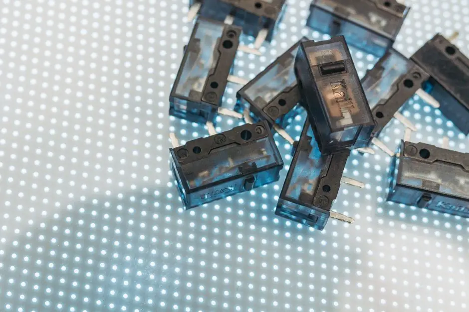
An unshielded (non-flush) inductive proximity sensor installed next to a steel bracket will false-trigger because the sensor's lateral electromagnetic field reaches the bracket and the coil interprets that metal as a target [S1].
Switching the same M12/M18/M30 housing to a flush (shielded) variant confines the field to the sensing face and lets the same bracket sit anywhere around the body without producing a trip [S1][S2]. Where extra range is mandatory, the practical workaround is to keep a metal-free zone of roughly three times the sensor's barrel diameter around the unshielded nose [S1][S2].
Why the bracket trips the sensor: field geometry, not electrical noise
Inside an inductive proximity sensor a coil drives an oscillator; the coil's alternating field is what eddy-current loss in a metal target damps, and that damping is the trip event. A shielded (flush) body wraps the coil in a metal collar that blocks flux from leaving the sides, so the field exits only through the front face and the body can be sunk into a steel block with no false trip [S1][S2][S5].
An unshielded (non-flush) body has no collar, so the field exits the front and the sides, forming a dome-shaped sensing region that reaches laterally into anything conductive within reach [S1]. When that "anything" is a mounting bracket, the bracket becomes a target, and the sensor fires even though the intended target is still outside its nominal range [S1][S2]. This is a sensing-field geometry problem, not an EMI or wiring problem, so shielded cable, ferrites, or twisted pairs will not stop it [S5].
Flush vs. non-flush vs. semi-flush: a four-criterion comparison
The four criteria that decide a bracket-side install are shielding, sensing distance, free-zone geometry, and mechanical protection. On shielding, only flush and semi-flush types are embeddable in surrounding metal; unshielded non-flush requires the bracket to stay clear of the nose [S1][S2].
On range, the same M12 body typically delivers about 1 to 20 mm in flush form and 2 to 40 mm in non-flush form, with non-flush usually 1.5x to 2x the flush distance for an identical housing [S1]. On free-zone geometry, flush sensors tolerate being pocketed in metal, while non-flush units need a metal-free collar around the nose of roughly three times the barrel diameter to keep the field from coupling into nearby structure [S1][S2]. On mechanical protection, a flush body sits level with or below the mounting surface and resists impact and contamination, while a non-flush nose projects beyond the threads and is more exposed to bump damage and dirt [S2][S5].
For semi-flush (quasi-embeddable) units the trade-off sits between the two: partial shielding, range closer to non-flush, and a reduced but non-zero free-zone requirement [S4]. The right pick is therefore driven by the bracket geometry: if the bracket is the only nearby metal and you can hold the free-zone, non-flush buys you range; if the bracket is the mounting surface itself, flush is the only reliable choice [S1][S2][S6].
Who this fix is for, and who it is not for
Flush shielded inductive sensors are the right call on conveyor side frames, machine-tool castings, and crane-hook detection brackets where the target approaches the face and the surrounding structure is steel [S2][S6]. They are also the right call inside any fixture where the sensor body is pocketed in metal and the only clear path is the sensing face [S1][S5].
Non-flush unshielded sensors stay the better pick when the target is small, the stand-off is large, and the surrounding bracket can be physically kept away from the nose, for example in open-air end-of-travel limit detection on a gantry where the bracket can be designed with an open pocket [S1][S3]. They are the wrong pick when the bracket wraps the sensor or passes within the free-zone, which on a typical 12 mm shielded M12 unit translates to a 5 mm nominal range and roughly 36 mm of clearance demand in the unshielded equivalent [S6]. Capacitive and photoelectric families sit outside this bracket-coupling problem and need their own mounting rules [S5][S7].
Field-installation signals that the bracket is the culprit
The diagnostic signature is straightforward: the output latches ON (or chatters) the moment the sensor is mechanically tightened into the bracket, with no target anywhere near the face [S1][S2]. Pulling the sensor out of the bracket by even a few millimetres of stand-off clears the trip instantly, which separates bracket-coupling from genuine EMI or wiring faults [S1][S5].
For 12 mm shielded M12 sensors specified for crane-hook detection, a 5 mm nominal range is the working point and the bracket must be designed around that face-only field, not around the housing [S6]. A second tell is asymmetric behaviour: the sensor trips when current is applied but does not de-latch cleanly when the bracket is still present, because the bracket acts as a continuous load on the oscillator rather than a transient target [S1][S4]. On capacitive sensor units the equivalent failure mode is condensation bridging the face, not bracket coupling, so the same diagnosis does not transfer [S7].
Mitigation rules that hold on the shop floor
Rule one: pick the housing around the bracket, not the bracket around the housing. If the sensor must sit in a steel pocket, use flush; if the bracket can be re-cut to give the nose air, non-flush buys roughly 1.5x to 2x the range for the same M-series body [S1][S2].
Rule two: when range wins, enforce the three-diameter free-zone. For an M18 non-flush unit that is roughly 54 mm of axial and radial clearance to the nearest bracket face, and the same multiplier applies to M8, M12, and M30 bodies in the same family [S1]. Rule three: separate the bracket material from the sensing field with a non-conductive spacer (machined plastic, PEEK, or fibre-filled nylon) if metal cannot be moved; the spacer breaks eddy-current coupling without changing the sensor [S1][S5]. Rule four: align the target to approach the face along the axis, not the side, because perpendicular approach gives a clean repeatable trip while a side-approach target wanders into the lateral-field zone and produces position-dependent triggering [S3].
Limits of the fix and what to monitor next
Shielding does not buy range, and a flush M12 with 5 mm nominal reach will still miss a target at 8 mm even with a perfect bracket design [S6]. Non-flush with a free-zone is sensitive to bracket retrofit, so any mechanical change on the machine must trigger a re-check of the clearance rather than an assumption that the sensor still meets spec [S1][S2].
Two signals to watch over the next quarter: vendors adding semi-flush (quasi-embeddable) variants for the M8/M12/M18/M30 range to close the range-versus-shielding gap, and a hardening of datasheet rules around minimum free-zone geometry expressed in sensor-diameter multiples rather than absolute millimetres [S1][S4]. For plants chasing higher uptime on conveyor and crane-hook applications, the immediate actionable item is to audit every unshielded inductive install against the three-diameter free-zone rule and re-spec to flush wherever the bracket cannot be reworked [S2][S6]. Related coverage of spec-driven retrofits on adjacent equipment, including conveyor idler and belt geometry decisions, shows the same pattern of geometric constraints overriding nominal sensor specs once a machine is in service.
Spec-level background on the components involved: proximity probe.