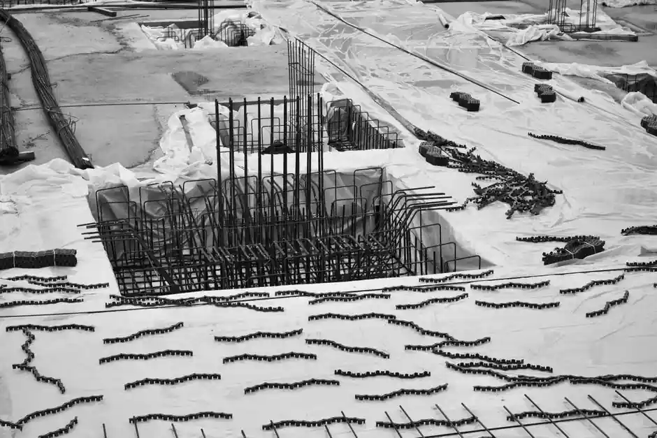
Tunnel primary support and final lining reinforcement is moving decisively away from lap splicing and welding toward mechanical rebar couplers, driven by the need to reduce congestion at lining joints and cut steel weight by the 15% typical of overlap zones [S2].
For tunnel works, the most common bar sizes are 16, 20, 25, 32 and 40 mm grade B500B/B500C, with 50 mm used in heavy TBM segments and crown reinforcement at cavern intersections; couplers must therefore cover the full 12-50 mm range and survive both shotcrete installation and segmental yard prefabrication [S1][S4].
Why Couplers Replace Laps and Welds in Tunnels
Lap splices for 32-40 mm bars in a 500 mm lining wall demand overlap lengths of roughly 50 bar diameters, which translates to 1.6-2.0 m of redundant steel per splice, congestion that blocks concrete flow and creates honeycombing near the inner face of segmental rings [S2]. Mechanical rebar couplers transfer full bar tension through a 70-180 mm sleeve, reducing steel consumption and the 20% dead-load penalty reported in heavily reinforced tunnel invert and crown sections [S1][S2].
Welding remains the alternative on some metro sites, but tunnel conditions (humidity, confined headroom, stray current from DC traction) make onsite welds hard to qualify; coupler installation is a cold process with torque-controlled verification, so it survives the shotcrete, EPB, and NATM environments where welds routinely fail UT inspection [S3][S4].
The Four Coupler Families Specified on Tunnel Sites
Engineers on tunnel projects typically choose between four mechanical splice families, each with a different failure mode and equipment footprint: [S1]
1) Straight threaded couplers (parallel or tapered thread) are the workhorse for diameters 16-40 mm in final linings and cross passages; connection strength reaches or exceeds parent bar ultimate, but they require a rebar threading machine on site and accurate thread rolling, with anti-corrosion coating specified where groundwater is aggressive [S1][S4].
2) Cold-extrusion (swaged) couplers are radial-pressed sleeves, used for 25-50 mm bars in heavy TBM segment cages, long invert pours, and cavern crowns where fatigue and seismic performance dominate; they tolerate larger bar-end tolerance but need a hydraulic extruder rated 50-80 MPa, which raises capex for small crews [S3][S4].
3) Grout-filled sleeve couplers (cementitious or epoxy grout) are preferred in precast segmental yards and column-to-lining connections, allowing rebar to be inserted without rotation and tolerating larger gap; cure time of 24-72 hours and grout QC are the trade-off [S1][S3].
4) MBT / bolted-saddle couplers are the emergency-repair and temporary-work option, installed with no bar-end prep and a hand ratchet, but capacity is closer to 80% of bar ultimate, so they sit outside the permanent-load path on most metro specifications [S3].
Selection Criteria: What Actually Matters Underground

Bar size and grade: the coupler must match bar diameter to within ±0.5 mm and be qualified for the rebar grade in use (B500B vs B500C have different ductility, so the splice must show ≥5% uniform elongation on qualification) [S3][S4].
Load path: ISO 15835-1 classifies couplers by performance under cyclic and seismic loading; for tunnels in seismic zones (typically PGA ≥0.2g) or for rail tunnels with live-load fatigue, the spec should call for "Type 2" (seismic) performance, which demands 4 cycles of inelastic strain up to ±5% without bar rupture or 50 mm slip [S2].
Environment: chloride-bearing groundwater, sulfate attack, and stray-current corrosion from DC rail systems push the spec toward epoxy-coated, galvanized, or stainless coupler bodies; threaded couplers in such service usually require a torque-checked end cap plus O-ring sealing, otherwise thread corrosion will compromise slip behavior within 10-15 years [S3][S4].
Installation setting: TBM segmental yards have stable power and a rebar cage jig, so threading or extrusion is straightforward; NATM/SEM top heading works have restricted headroom and intermittent ventilation, which rules out high-current extruders and pushes the choice toward threaded or grout-filled systems that can be hand-torqued or pumped through small-diameter hoses [S1][S3].
Comparison: Threaded vs Cold-Extrusion vs Grout-Filled for Tunnels
A 32 mm B500C bar at a typical tunnel cross passage illustrates the trade-offs across four decision criteria (data synthesised from [S1][S3][S4]):
Straight threaded: tensile capacity at or above bar ultimate (≈620 MPa), installation time roughly 2-3 min per splice with a portable rebar threading machine, equipment cost low, site suitability good for both segmental yard and confined heading.
Cold-extrusion: tensile capacity at or above bar ultimate, installation time 5-8 min per splice due to multi-pass pressing, equipment cost high (hydraulic extruder plus generator), site suitability best in yard work and heavy-bar cavern crowns, marginal in tight headings.
Grout-filled: tensile capacity at parent bar level after grout cure, installation time 10-15 min plus 24 h cure, equipment cost low, site suitability excellent for precast segments and column-to-lining connections where bar rotation is impossible.
Installation and QC Workflow on a Tunnel Ring
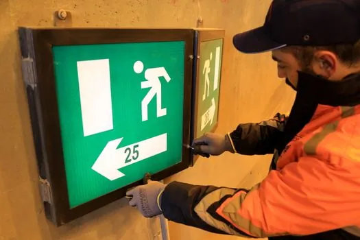
For a 32 mm threaded splice in a 300 mm-thick segmental ring, the engineered sequence is: cut the bar square with a rebar cutter, cold-roll the thread with a calibrated threading machine, fit the half-coupler, hand-tighten, then torque to the supplier's value (typically 280-340 N·m for 32 mm), mark the joint with a torque paint stripe, and record the operator ID and torque value on a traceability sheet per ACI 318 §25.4 [S1][S3].
QA sampling: 1 in 25 couplers receives a field tensile pull to ≥125% of specified yield, and 1 in 50 a full ISO 15835-1 Type 2 cyclic test if the tunnel is in a seismic zone; failed couplers trigger re-test of the lot plus a root-cause review of the threading die and operator certification [S2][S3].
Failure Modes and Spec Pitfalls to Avoid
Three failure modes drive the majority of coupler rejections on tunnel projects: (1) thread stripping from worn dies or undersized thread engagement, visible as coupler body elongation under load with no bar thread fracture; (2) slip at the bar-sleeve interface, caused by grease contamination or under-torquing, with measured slip often exceeding the 0.1 mm ISO 15835 limit; (3) grout voids in sleeve couplers, detectable only by borescope or destructive testing, and responsible for most of the in-service splice failures logged on metro projects in the past decade [S1][S2][S3].
Two spec pitfalls to flag in the procurement document: never accept "conforms to ISO 15835" without the named Type 1 or Type 2 classification, and never mix parallel-thread and taper-thread couplers from different suppliers on the same pour, since thread profile and torque values are not interchangeable [S2][S4].
Trackable Signals Through 2026
For related field guidance on parallel tools, see this rotary hammer selection for tunnel construction: a spec-level guide and this rebar threading machine picks for demolition: diameter, drive, site fit.