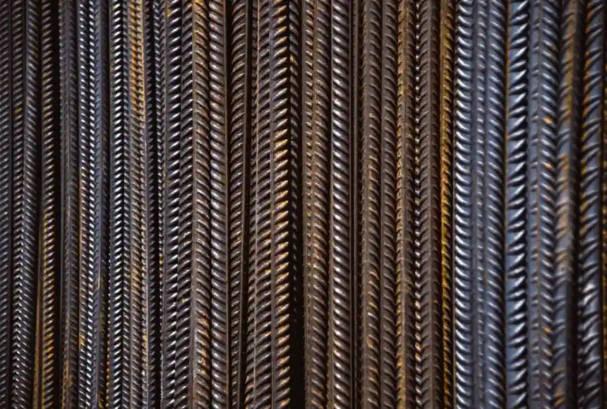
A rebar straightener inspection checklist in September 2026 should run a five-subsystem audit (mechanical, electrical, hydraulic/pneumatic, straightness output, and operator safety) tied to ASTM A615/A706 grade verification, with a pass threshold of ≤3 mm/m deviation on straightened bar stock [S2][S3].
Scope covers stationary shop straighteners from 6 mm to 40 mm rebar capacity, including vertical and horizontal pull-through machines. The procedure complements paperwork checks for rebar stamps, mill certificates, and heat-number traceability [S2][S3], and pairs naturally with downstream rebar bender and rebar cutter acceptance routines.
Paperwork and Material Traceability Gate
Mill certificate cross-check against design grade is the first gate: bar stamps, heat numbers, and bar grade identification must match the purchase order and approved drawing schedule before any mechanical inspection begins [S2][S3]. The auditor should record heat number, manufacturer, nominal diameter, and grade on the checklist with time-stamped photos of the bar tag [S4].
For laboratories running ASTM-based qualification under CCRL scope, sample bars must be sized between No. 3 and No. 20 (≈9.5 mm to 51 mm) to satisfy A370, A615, A706, A996, and E8 demonstrations, with bend-test pins matched to the bar diameter presented [S5]. Field crews handling the same feed stock on a rebar straightener should retain two sample bars of the same lot for any subsequent mechanical retest.
Mechanical Subsystem: Rolls, Pinions, and Wear Surfaces
Roll inspection is the heart of straightener health: each straightening roll must be measured for diameter, surface hardness, and concentricity, with any roll showing fluting, brinelling, or lip wear rejected or scheduled for re-machining [S1]. Lubrication state on roll bearings and pinion gears should be verified by sight glass, and gear-mesh backlash should be checked with a dial indicator against the OEM service tolerance (commonly 0.10–0.30 mm on small shop units).
Frame and alignment are the next mechanical gate: verify the entry guide, exit guide, and pinch-roll parallel to the machine centerline within 1 mm over 1 m using a dial gauge on a reference bar, and confirm anchor bolts remain torqued to spec with no concrete cracking around the base [S1]. A short bar fed by hand through the unit at no-load should run true; any wandering or chatter indicates misalignment before the straightness measurement is even attempted.
Electrical, Controls, and Hydraulic/Pneumatic Audit
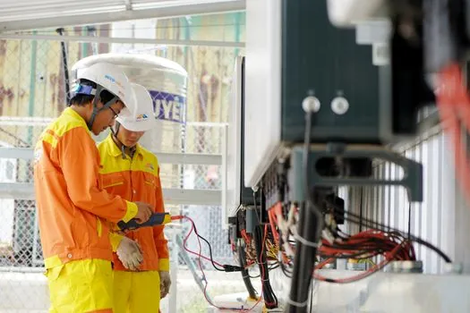
Electrical isolation is the first safety check: verify the main disconnect locks out, control circuits are de-energized and tested dead with a calibrated meter, and all cables, plugs, and motor terminations show no chafing, heat discolouration, or exposed copper [S1]. The control panel buttons, E-stops, and interlocks must each be function-tested; emergency-stop response should drop power to the drive within one revolution of the drive shaft, and a 24 V control fuse should be present to protect the logic circuit [S1].
Hydraulic or pneumatic actuation (on powered-pinch and cut-to-length variants) requires a separate audit: HPU oil level, filter condition, hose integrity, and accumulator pre-charge pressure must all fall within the OEM range, and any cylinder rod showing scoring or seal weepage must be tagged for rebuild [S1]. Where the straightener is integrated with a rebar cutter line, the interlock sequencing between straightener feed, shear, and discharge ramp must be tested under no-load and live-bar conditions.
Straightness Output Acceptance Test
The pass/fail output metric is residual bow on a 1 m sample laid on a flat reference bed: deviation should not exceed 3 mm/m for grade 40/420 and 2 mm/m for grade 60/520 stock destined for lap-splice-critical zones [S2][S3]. For 10 m and longer raft bars used in horizontal mats, run a longer sample and check mid-span camber with a taut string line, accepting mid-span offset ≤ L/1000 where L is the sample length in mm.
A 10% random sample of straightened bars should be re-measured with calipers for diameter at three points along the length to confirm the straightening process has not necked the bar below nominal minus the mill tolerance band [S2][S4]. Any bar that flunks bow or diameter is re-routed to scrap or to a slower feed-speed pass; do not re-straighten a bar that has already been through the machine more than twice, because cold work accumulation can push yield strength outside the ASTM A615/A706 envelope [S2].
Safety Guards, Operator Documentation, and Acceptance Sign-Off
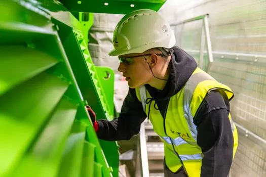
Safety-guard verification mirrors the bar-cutter checklist: all fixed and interlocked guards installed and fastened, E-stops tested, no exposed wiring, machine grounded, and legible signage in place [S1]. Operators must have documented training on the specific straightener model and be issued the appropriate PPE (cut-resistant gloves, ANSI Z87.1 eye protection, hearing protection above 85 dBA exposure), with PPE issue logged on the inspection sheet [S1].
Final sign-off requires the inspector to record readings on a rebar-and-reinforcement-style checklist that also captures cover, spacing, anchorage, and lap-splice compliance for the placement pass, since the straightened bar is staged for pour within the same shift [S3]. For raft foundations, additional 5 mm blinding-level and 10 mm grid-setout tolerances apply before the first mat is laid [S4]. A signed checklist with inspector name, date, and photo evidence is the traceable artefact for QA handover; any red-line item blocks the next concrete pour until corrected and re-verified [S3][S4].
Trackable signals for the next maintenance window: monitor the roll-bearing temperature trend with an IR spot reading at every shift, and log the kWh drawn per tonne straightened so a drift above the 4.0–5.5 kWh/t band flags a degrading roll or feed-motor issue; the September 2026 audit cycle for similar shop equipment is documented across V-Process molding line spec guides and forklift spare-part replacement maps for cross-equipment calibration logic.