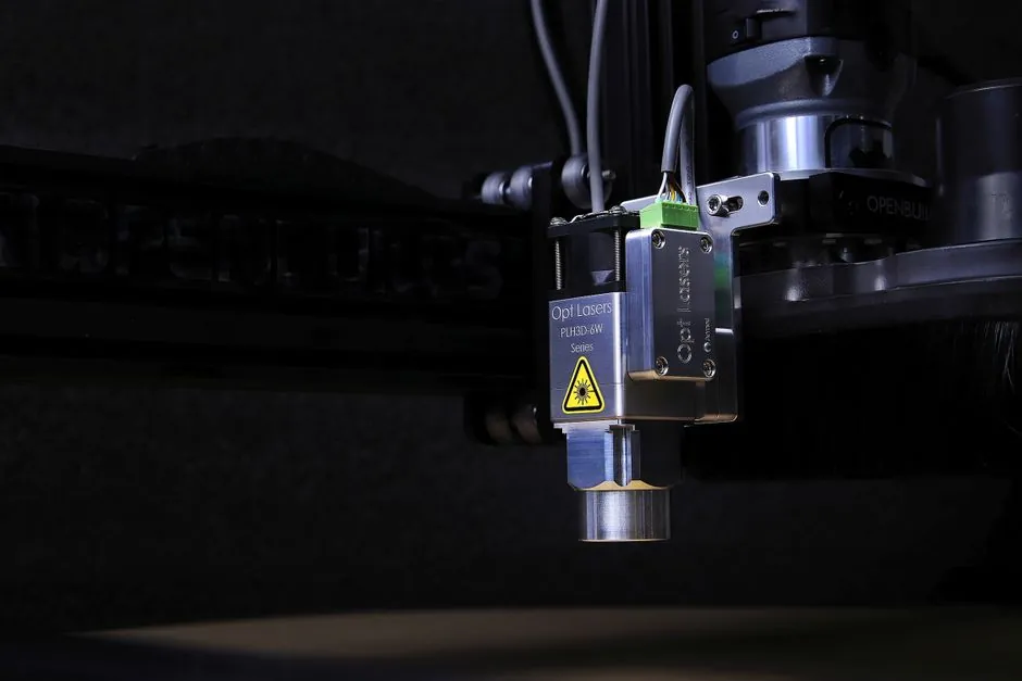
A red-frame guide beam is the standard dry-run preview on galvo-scanned laser markers: a visible red laser (commonly 650 nm) traces the intended marking field on the part before the IR working beam fires, so the operator can confirm placement without consuming the part [S1].
Because galvo laser markers have a fixed output position and steer the beam with mirrors, the workpiece is what moves under the head, making a positioning aid essential for anything below roughly 50 mm field size or for curved, irregular, or high-mix parts [S1][S7].
Three preview modes: Boundary, Shape, and Contour
Boundary mode traces the smallest axis-aligned rectangle enclosing all design elements, runs in well under a second, but does not represent L-shaped, circular, or multi-line artwork faithfully [S1]. Shape mode traces a minimal closed path that encloses the artwork and is more representative of the actual mark footprint at the cost of slightly longer preview time on complex vectors [S1]. Contour mode follows the exact outline of every curve and edge, gives the most accurate dry-run, and takes the longest to trace, but is the only mode that lets the operator verify registration on fine text below 1 mm height [S1]. For parts with logos, regulatory marks, or serial numbers, Contour is the default; for rough centering on blanks, Boundary is acceptable [S1].
How the red beam is generated and aligned
The red pointer is a coaxial low-power diode that shares the galvo scanner optics with the working beam (commonly 1064 nm fiber, 10.6 µm CO2, or 532 nm green), so the visible trace and the IR mark share the same X/Y path with no parallax offset at the working distance [S1][S7]. Operators jog the part on a fixture or move the galvo origin in software until the red trace falls inside the target zone, then lock the position before firing [S5]. Because fiber and YAG markers typically deliver 100-120 ns pulse widths at 20-30 W, even a single misplaced pulse will leave a permanent mark, so the red preview is the only zero-cost verification step [S3].
When red preview is enough, and when it is not

Red-frame preview is the right tool for flat, regularly shaped parts, for batch runs where the operator can repeat a fixture position by eye, and for artwork with features above 1-2 mm [S1]. It is not enough for sub-millimeter registration, transparent or highly reflective surfaces where the red scatter is too weak to see, and parts with runout or dimensional tolerance above roughly ±0.1 mm, where a camera vision system reads fiducials and corrects origin in software [S1]. For medical-device UDI marks, aerospace traceability, and any application covered by ISO/IEC laser safety Class IV rules, camera or mechanical-pin registration is the defensible choice over red preview alone [S4].
Mechanical fixtures and jigs that complement the guide beam
Mechanical fixtures convert a good first-shot preview into repeatable batch output: locating pins, v-blocks for cylindrical parts, and vacuum chucks hold the workpiece within roughly ±0.05 mm so the red frame lands in the same spot on part 1 and part 10,000 [S1]. For high-volume lines, a nests plate with part-specific cavities is faster than re-teaching the preview every changeover, and it pairs with the linear guide that carries the part under the galvo head on automated cells [S1][S7]. Where parts have multiple mark zones, multi-cavity fixtures let one camera read several origins in a single pick-and-place cycle rather than re-aligning per cavity [S1].
Comparison: preview methods and when to pick each
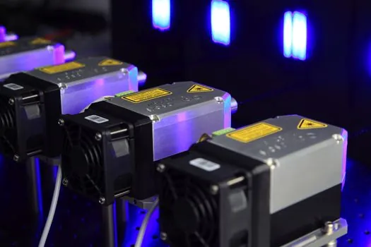
Across the four common positioning methods for galvo laser markers, the trade-off is speed, hardware cost, and placement accuracy [S1]. Red-frame preview is essentially free (built into the marker software) and accurate to roughly ±0.1-0.2 mm by eye, which is the lowest-cost option for low-mix work [S1]. Mechanical fixtures (pins, jigs, vacuum plates) add fixture build cost but bring repeatability to roughly ±0.05 mm with no software change. Camera vision systems add camera, light, and software cost but reach roughly ±0.01-0.02 mm and read part-specific fiducials, which is the only option for transparent or reflective parts where the red scatter disappears. For very small marks, the same optics that carry the red beam are described in the crossed-roller guide family of articles on galvo head stability, since any angular drift shows up as a misregistered mark at the workpiece.
Common faults traced back to the guide beam step
Three recurring field complaints all trace to the preview step. First, off-center marks on small parts: the red frame looked centered to the operator but the part was rotated 2-3 degrees, so the firing pulse strays outside the target zone; fix by switching from Boundary to Contour mode so the rotation is visible [S1]. Second, drift across a batch: first part looks right, parts 50-100 walk off, usually because the fixture is relying on a flat surface and the part has a small burr or spring-back; fix with a locating pin or a color-mark sensor to detect the leading edge before the galvo fires [S1][S5]. Third, weak or invisible red on shiny metals: the working distance is wrong or the red diode is failing, and the operator marks blind; fix by re-measuring the focal standoff and confirming the red dot at low magnification before any production run [S1][S3].
Safety and class rules that govern the red pointer itself
The red guide diode is a Class II or 3R visible laser at most, but it sits on the same optical path as a Class IV marking beam, so CDRH Class I (fully enclosed) or Class IV (open, requires laser safety glasses) classification governs the whole machine, not the pointer [S4]. Operators must keep the enclosure interlocked when the IR beam is armed even though the red beam itself is safe to view, and the laser level family of alignment articles covers the same coaxial-pointer principle used in larger marking cells. The red diode failing while the IR beam still fires is a known failure mode, so a periodic pointer-versus-mark check (mark a test card, overlay the burned mark on the red trace) belongs on every PM route.
Trackable signals for the next cycle: wider rollout of camera-vision positioning on sub-30 mm fields, where red preview accuracy no longer meets UDI and aerospace traceability requirements, and replacement of fixed-pulse 100-120 ns fiber sources with variable-pulsewidth heads where the same preview step also has to validate ablation versus engraving energy on a part-by-part basis [S3][S1]. For a deeper dive on how galvo steering differs from gantry-style laser profiler heads on conveyor lines, the companion piece on Integrated Stepper Motors: Built-In Drive, Encoder, and Fieldbus Choices covers the motion side of the same marking cell.