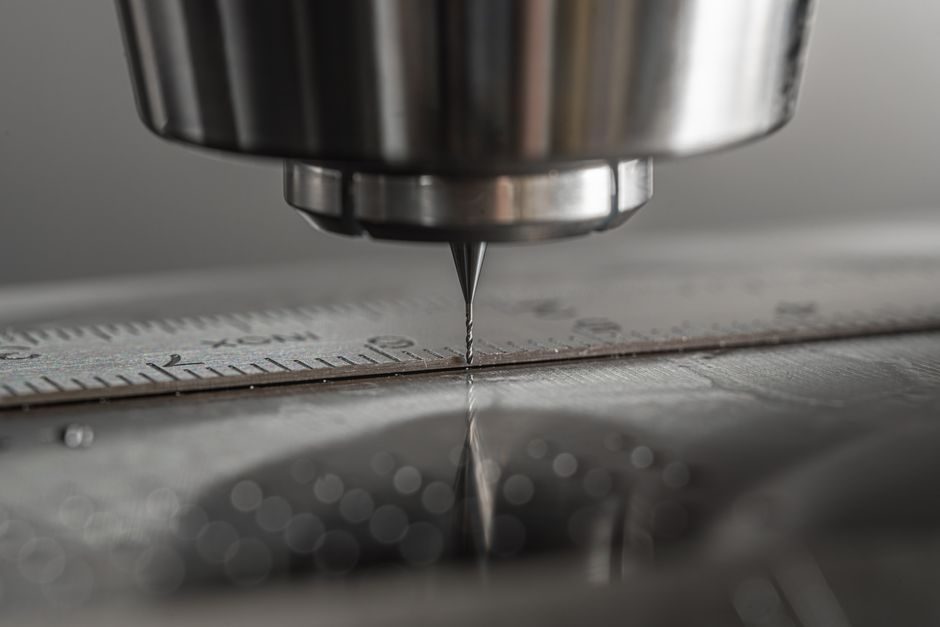
A riser cutting machine is a foundry auxiliary built to shear off solidified risers, gates, and feeder heads from castings after knockout, and the category spans at least five distinct machine architectures differentiated by drive type, automation tier, and maximum riser neck diameter [S1].
Pneumatic, hydraulic, servo-CNC, and manual lever platforms each address a different mix of cycle-time, riser diameter, and operator-skill constraints, and the wrong class typically shows up as bent cut-off wheels, incomplete severance, or excessive cycle-time drag on the pouring line [S1].
Drive-Power Classification: Pneumatic, Hydraulic, and Servo
Pneumatic riser cutters use 0.5–0.8 MPa shop-air cylinders to drive a linear cut-off blade and are the default on small-to-mid iron foundries handling riser neck diameters from roughly 20 mm up to 80 mm, where cycle time per cut is typically 3–6 seconds [S1].
Hydraulic riser cutters run system pressures in the 10–21 MPa band and deliver cutting forces commonly in the 5–30 kN range, making them the workhorse for riser necks above 80 mm and for high-hardness steel-casting applications where pneumatic stall is a real risk [S1].
Servo-CNC riser cutters replace the fixed-stroke pneumatic/hydraulic cylinder with a servo-driven lead-screw or rack-and-pinion axis, and on automated cells they hold cut-length repeatability inside ±0.5 mm while supporting recipe-based parameter switching between part numbers — a feature pneumatic machines cannot match without mechanical re-tooling [S1].
For a broader view of how cutting machines are classified across materials, the cutting machine reference page covers wire, tube, sheet, and billet variants in parallel architecture.
Automation Tier: Manual, Semi-Automatic, and Robotic Cell
Manual lever or foot-pedal riser cutters still ship in volume for job-shop foundries pouring under 200 t/day, and the operator visually locates the riser neck, actuates the clamp, and trips the cut — adequate when labor cost is low and mix variance is high [S1].
Semi-automatic riser cutters add a powered clamp plus a two-hand safety actuation, holding the operator's role to part loading and unloading only, and they typically cut cycle time per riser to 2–4 seconds versus 6–10 seconds on a manual lever machine [S1].
Fully automatic cells integrate a conveyor or robotic pick-and-place feeding the cutter, with downstream shot-blast and inspection stations; these cells are economically justified above roughly 1,500 t/year of single-part-number throughput, where manual or semi-auto labor content becomes the bottleneck [S1].
On wider plant-floor integration questions, the core machine reference page covers how core-setting and riser-cutting cells are typically sequenced inside a foundry line.
Cutting-Action Architecture: Shear, Abrasive Wheel, and Saw
Shear-blade riser cutters use opposing straight or curved blades and rely on impact plus slide to fracture the riser neck; they are favored on gray and ductile iron where the neck shears cleanly, and blade life is typically 5,000–15,000 cuts before re-grinding depending on neck diameter and iron grade [S1].
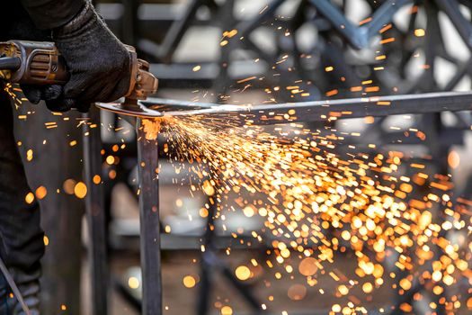
Abrasive-wheel riser cutters mount a high-speed cut-off wheel (typically 300–600 mm diameter running at 2,000–3,800 rpm) and are the preferred architecture for steel castings and for riser necks above 100 mm where shear blades chip or bind [S1].
Saw-type riser cutters (band-saw or cold-saw derivatives) appear on heavy steel foundry floors and on riser necks above 150 mm; they trade cycle time for a clean, low-burr cut that often eliminates a downstream grinding pass [S1].
Foundries evaluating abrasive versus shear should note that abrasive-wheel change-out is typically every 80–300 cuts versus the multi-thousand-cut life of shear blades, so the consumable-cost line item flips sharply between the two architectures [S1].
Riser Diameter and Material Mapping
Small-riser class (20–50 mm neck): pneumatic shear units dominate, with manual or semi-auto clamping, and a 0.37–1.5 kW motor is typical; cycle times under 3 seconds are achievable on ductile iron [S1].
Mid-riser class (50–120 mm neck): hydraulic shear or small abrasive-wheel units are specified, with motor power in the 2.2–5.5 kW band and cutting force in the 10–25 kN range; this is the most volume-sold band globally [S1].
Large-riser class (120–300 mm neck): hydraulic abrasive or saw-type units are mandatory, motors reach 7.5–15 kW, and the machine frame is typically cast-iron or fabricated steel with a riser-clamp force above 30 kN to prevent part slippage during the cut [S1].
For sourcing context on adjacent foundry equipment, the riser cutting machine reference page consolidates selection criteria and typical OEM model families.
Selection Criteria: For Whom Each Class Fits
Small job-shop iron foundries pouring under 200 t/day with high mix variance should specify a manual or semi-automatic pneumatic shear unit, accepting longer cycle time in exchange for capital cost under roughly USD 8,000–15,000 and the ability to re-tool in under 10 minutes [S1].
Mid-volume ductile-iron and steel foundries in the 500–3,000 t/day band should specify a hydraulic shear or abrasive-wheel semi-automatic unit, where the higher cutting force removes the stall risk on harder riser necks and where the USD 20,000–60,000 capital band is amortizable inside 18 months on labor savings alone [S1].
High-volume single-part-number steel foundries above 3,000 t/day should specify a servo-CNC abrasive or saw-type cell integrated with a robotic loader, and should plan for the USD 120,000–400,000 capital band plus a dedicated controls-engineering scope for recipe management and downstream hand-off [S1].
Foundries that should NOT specify a servo-CNC cell include those with part-number mix above roughly 30 active SKUs per month, where recipe management overhead exceeds the cycle-time gain; pneumatic or hydraulic semi-auto units remain the lower-TCO choice in that scenario [S1].
Limitations, Failure Modes, and Maintenance Windows
Shear-blade units fail most often by chipping of the cutting edge when fed into a misaligned riser neck, and preventive blade rotation or re-grinding every 1,000–2,000 cuts on steel risers is the standard maintenance gate [S1].
Abrasive-wheel units fail most often by wheel glazing or by spindle-bearings degradation from cut-off dust ingress, and a typical maintenance gate is bearing inspection at 2,000 hours and dust-extraction verification on a weekly basis [S1].
Hydraulic units carry the additional failure surface of seal life (typically 3,000–6,000 hours on the cylinder seals at 10–21 MPa) and oil-temperature drift above 60 °C, which degrades cut-force repeatability and is a frequent cause of incomplete-severance defects on production lines [S1].
Pneumatic units are constrained by shop-air pressure stability; a drop below 0.5 MPa will stall the cut and produce bent or incomplete severances, so a pressure-regulator with alarm and a receiver tank of at least 100 L is standard fit on a production-grade pneumatic riser cutter [S1].
Standards, Sourcing, and Trackable Signals
Riser cutting machines are not governed by a single dedicated ISO or EN standard; instead they are typically designed to general machinery safety standards including ISO 12100 for risk assessment and EN 60204-1 for electrical equipment of machines, with the two-hand control requirement on semi-auto units aligned to ISO 13851 for the safeguarding of two-hand control devices [S1].
For buyers, the practical procurement gate is a documented type-test of cutting force at maximum rated riser neck diameter, plus a CE or equivalent declaration citing ISO 12100 conformity, rather than a foundry-specific product standard [S1].
Trackable signals to watch on the 2026 procurement side include servo-drive price erosion (which is closing the capital gap between hydraulic and servo-CNC units), tightening European CE reclassification of older pneumatic units, and growing demand for abrasive-wheel dust-extraction packages as foundries face stricter workplace-exposure rules [S1].
For a comparison of how adjacent process equipment is classified under similar engineering logic, the coding machine and labeling machine reference pages show the same drive-tier and automation-tier breakdown applied to downstream packaging lines.
Background reading: FIBC Bulk Bag Types and Classifications: An Engineer's Spec Map.