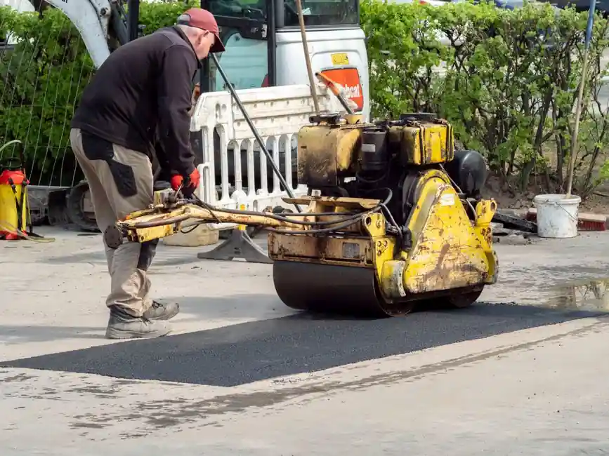
A road roller installation is dominated by the drum lift-and-align step on a 360° bearing-supported shaft, a process that requires crane rigging rated to the drum mass, slow angular correction, and bolt-up verification before any compaction pass is attempted [S2].
Two roller families define the field: smooth-drum static rollers and tire-type rollers, both of which compact by self-weight, plus vibratory rollers that add a centrifugal exciter inside the drum for deep lift compaction [S1]. Pre-run checks on leaks, gauges, vibration frequency, and clutch condition are non-negotiable before ignition, because the hydraulic propulsion loop and servo valves are exposed to wear from the first start [S3].
Drum installation: rigging, shaft alignment, torque sequence
Crane selection for a drum change is the first decision point, and the rule of thumb is to use a rigging capacity of at least 1.25× the drum mass plus a margin for the eccentric vibrator mass that sits inside most smooth-drum shells [S2]. The replacement drum is lifted steadily to the mounting position, with the operator adjusting angle and height to align the shaft bore with the side-frame housing; misalignment at this stage is the leading cause of premature roller bearing failure on re-commissioned units, because the eccentric mass will impose cyclic side load on the inner race the moment vibration is energised [S2]. Bolt-up must follow a star pattern, and the source guidance treats slow, incremental angular adjustment as the controlling variable rather than raw lift speed [S2].
For vibratory drums, the eccentric weight assembly and the vibration-damping devices are mounted before any compaction pass, since direct vibration on a hard surface before the rubber buffers are seated will mark the drum shell and crack the isolators [S1]. Drum-to-frame clearance should be checked with a feeler gauge across the wear-ring gap; a 0.5–1.5 mm running clearance is typical for production single-drum rollers, although the source materials do not quote an OEM figure and site-specific manuals govern [S2].
Drive-train and clutch commissioning: static, vibration, direction-change
Road rollers carry two clutches, the main clutch and the direction-change clutch, plus a vibration clutch on vibratory models, and the engagement sequence is what determines whether a 10-year unit survives a 5-year duty cycle [S1]. The main clutch pedal must be depressed to cut power before the brake pedal is applied in any emergency stop, and the reverse order applies on release, otherwise the driveline absorbs a torsional shock each stop that the universal-joint and roller chain drives on the axle are not designed to damp [S1].
Direction change requires the operator to move the handle to centre and wait for the machine to stop fully before commanding reverse; forcing a direction change while the drum is still rolling forward will shear the direction-clutch splines [S1]. If the direction-change clutch or the vibration clutch is observed to slip during commissioning, the source guidance is explicit: stop the machine immediately, disengage the main clutch, and resolve the fault, because running a slipping clutch at high speed burns the friction plate within minutes and turns a 200 USD service job into a 2,000 USD teardown [S1]. The standard symptom-to-cause-to-action chain here is: slipping clutch → low contact pressure or oil contamination → re-adjust linkage or replace friction disc; do not continue to operate under slipping [S1].
Vibration circuit and eccentric settings: frequency, lead-in passes, hard-surface lockout

Most vibratory rollers carry a control panel where frequency, amplitude, and on/off are set electrically and act on hydraulic servo valves that gate flow to the propulsion motors and the eccentric-drive motor [S3]. Frequency settings left by a previous operator are a common commissioning failure, because two adjacent machines on the same asphalt mat running at different frequencies will produce a non-uniform density profile that core-testing will catch; the cure is a documented handover of vibration settings at every shift change [S3].
The compaction sequence on loose material follows a fixed recipe: 1 or 2 static passes first to seat the aggregate, then vibratory passes for density, and the vibratory function must be engaged or disengaged while the roller is still moving, not at standstill, because starting the eccentric from a dead stop on a hard surface transmits a shock load through the linear guide slides on the exciter mount and will crack the mounting bracket within hours [S1]. Direct vibration on hard surfaces, that is concrete slabs, cured asphalt, or steel decks, is prohibited in the source guidance as a hard rule, with the explicit reason that the vibration-damping devices and the eccentric bearings are not rated for that impact load [S1].
Slope operation, multi-roller spacing, and long-distance transfer
Slope work is where most commissioning-period rollovers happen, and the protocol is to stop the machine, select the appropriate gear on level ground, then enter the slope without further shifting, with low gear mandatory on descents to use engine compression braking rather than the service brake [S1]. High-speed operation on inclines is paired with a no-sharp-turns rule, because a steered roller on a cambered surface has a tipping line that moves toward the downhill side as speed rises [S1].
When multiple rollers work the same lift, the minimum spacing is 3 m, set explicitly to prevent collision and steering interference between machines tracking each other on a confined mat [S1]. Long-distance transfer of a roller under its own power is discouraged; the source guidance is to use professional low-bed transport, because road-speed travel on public highways stresses the articulation joint, the drum bearings, and the crossed-roller guide elements in the steering knuckle far beyond their designed duty cycle [S1]. For a primer on adjacent heavy-equipment rigging, see the crawler crane vs gantry crane 2026 spec map for capacity, terrain, and site fit, which covers the crane side of drum-change work. Differential-lock engagement is a related slope-protocol tool: differential unlocked in normal work, locked only when the rear wheels are slipping in mud or on loose stone, then released as soon as traction returns, because a locked differential on a steered roller tears the surface [S1].
Pre-start inspection, PPE, and acceptance criteria

The pre-start checklist is operator-side, not just paperwork: full PPE including helmet and safety goggles, leak check on the hydraulic propulsion loop, gauge sweep across engine, hydraulic, and vibration circuits, and a walk-around for loose fasteners on the drum wear-ring bolts [S3]. Acceptance criteria for a successful installation are: no hydraulic leak at drum-shaft seal after 10 minutes of idle, no clutch slip on a 30-second full-throttle direction-change test, vibration-damping isolators seated with no daylight visible between rubber and mounting plate, and differential lock engaging and disengaging cleanly at standstill [S1][S3].
When the unit fails any of those four checks, the source guidance is to escalate, not to commission, because a roller with a slipping clutch or a weeping drum seal is the failure mode that turns a handover into a warranty dispute [S1]. The road roller itself sits in the broader compaction-and-paving road roller category alongside plate compactors and tandem rollers, and the same acceptance logic (no leaks, no slip, no hard-surface vibration) applies across the family.