
Select a desalination safety relief valve only after sizing the protected system and confirming the valve can open at set pressure, relieve the required flow at allowable overpressure, and discharge without creating a greater hazard.
The duty spans seawater, concentrated brine, membrane-feed and permeate systems, chemical dosing lines, and thermal or auxiliary equipment, with metallurgy, fluid properties, back pressure, installation, and maintenance requirements driving the final choice.
Separate code relief from process control
A safety relief valve protects vessels, piping, and other equipment from pressure exceeding the design basis by the permitted amount; it is not a regulating valve and must not be used to control normal operating pressure [S2]. For this reason, a relief valve is normally installed as close as practical to the protected vessel, boiler, pressurized equipment, or blocked-in piping [S6].
Desalination systems require two separate decisions. The first is whether the protected equipment needs a pressure-relieving device at all. The second is whether that device must be a spring-loaded safety valve, a pilot-operated valve, a rupture disc combined with a relief valve, or another qualifying arrangement. API RP 520 sizing rules address flanged spring-loaded and pilot-operated safety relief valves with a D-T orifice, while the Baker Hughes sizing reference also provides separate treatment for rupture-disc combinations and API fire sizing [S5].
Do not use an adjustable thermoplastic pressure-maintaining valve as the primary overpressure device merely because it is labeled a relief valve. The EF718 is a direct media-operated, diaphragm-controlled device intended for relief and upstream-pressure stabilization in liquid systems, with a DN8–DN50 range and an adjustable pressure range of 0.5–10 bar [S3]. That product description does not replace code qualification for a life-safety overpressure function.
Build the sizing basis before selecting a model
Determine the protected system MAWP, the applicable allowable accumulation, the design overpressure scenario, required relieving capacity, fluid phase, fluid properties, and discharge conditions before comparing valve models [S1][S5]. API RP 520 uses set pressure and overpressure to establish the sizing basis, while manufacturer data define the certified relieving capacity at the specified overpressure [S5].
For liquid relief, record whether the required flow is two-phase, whether flashing or cavitation is credible, the fluid temperature, and whether the relief stream will flash to vapor after leaving the valve. The Baker Hughes reference includes separate sections for API formulas, ASME formulas, correction factors, fluid properties, standard orifice areas, superheat factors, rupture-disc combinations, and API fire sizing [S5]. These inputs cannot be replaced by nominal valve size or by a generic seawater flow estimate.
The sizing calculation must also establish whether the selected valve can pass the calculated capacity at the required overpressure without instability. A valve may have a nominal size and pressure rating, yet still fail the duty because of its actual certified capacity, back-pressure limits, fluid-temperature correction, or an unsuitable inlet configuration [S1][S5].
Compare spring-loaded, pilot-operated, and rupture-disc arrangements
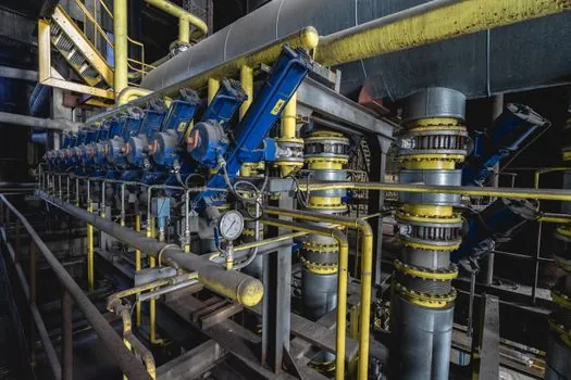
A spring-loaded safety relief valve is held closed by spring force and opens in response to vessel pressure [S2]. Pilot-operated valves use a pilot to control a larger main-valve opening and are evaluated when their operating characteristics, particularly inlet and outlet pressure limits, match the installation [S5]. A rupture disc plus relief valve can isolate the valve from corrosive or fouling process fluid, but the combination must be sized and rated as an assembly rather than by adding nominal capacities [S5].
This comparison is a selection screen, not a final selection. The governing sizing calculation and the manufacturer-certified limits decide which arrangement is acceptable.
Match seawater and brine construction to the actual fluid
Desalination material selection must start with the fluid, not the generic label “seawater.” Check chloride concentration, temperature, treatment chemicals, oxidizing conditions, and whether the valve sees raw seawater, antiscalant, cleaning chemicals, or concentrated brine [S3][S4]. Stainless steel and titanium are identified as corrosion-resistant construction options for seawater service, but the selected grade still requires compatibility verification [S4].
For polymer valves, inspect every wetted component; the EF712 and EF718 families have configuration-dependent PVC-U, PP, or PVDF bodies [S3]. These combinations are not automatically interchangeable. The fluid composition and concentration, pressure, temperature, diaphragm and sealing materials, connections, and complete-valve pressure-temperature capability must be checked together [S3].
Thermoplastic construction is generally most relevant to compact liquid-service systems where corrosion resistance and compatibility with plastic piping justify it. It is not the automatic answer for a high-pressure membrane plant or high-temperature thermal service. Metallic, lined, or thermoplastic constructions may all be considered, but the selected body and trim must be supported for the actual duty [S3].
Set pressure must satisfy the protected-system limits
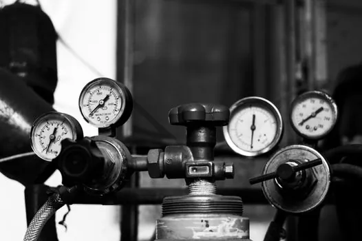
The valve set pressure, governing MAWP, and permitted overpressure must be aligned so that the valve opens before the protected system exceeds its allowable pressure [S1][S2]. The selection record should state the MAWP, set pressure, design pressure, allowable accumulation, and calculated overpressure rather than listing only the valve pressure class.
Thermoplastic dosing valves illustrate why model-level data matter. EF718 covers DN8–DN50 with an adjustable range of 0.5–10 bar. EF712 covers DN10–DN100 with an overall adjustable range of 0.3–10 bar, although the exact range depends on size and configuration and DN100 versions are available up to 6 bar [S3]. A selected size must therefore meet both the required flow and the required set pressure.
For normal process regulation, a separate control or pressure-retaining function may be required. A pressure relief valve must remain capable of opening at its predetermined set pressure and flowing its rated capacity at the specified overpressure, even when power is lost, because the process fluid is its sole operating power source [S2].
Verify discharge, installation, and environmental constraints
Model selection is incomplete until the discharge system is evaluated. The routing must handle the relieving phase without unsupported back pressure, excessive velocity, vibration, hydraulic hammer, or discharge back into an occupied or unsafe area. Inlet and outlet piping must not add excessive friction or react loads that impair operation, and the valve should be located as close as practical to the protected equipment [S6].
For seawater systems, evaluate chloride exposure, salt deposits, biofouling, and the corrosion allowance of associated piping and supports. Seawater systems operate with elevated pressures and changing conditions, so corrosion resistance, wear resistance, high-pressure capability, and ease of disassembly and cleaning affect long-term reliability [S4]. A valve that cannot be inspected and serviced without extensive shutdown is a poor maintenance choice even if its initial material specification is sound.
Confirm whether the discharge requires atmospheric, closed, or vacuum conditions. The related pressure-vacuum relief valve handles a different venting duty and should not be substituted for a required liquid or gas overpressure valve. Likewise, an air-release valve is intended for air or gas management, not protection against equipment overpressure.
Commission, test, and maintain the selected valve
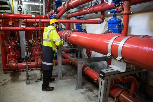
Purchase the valve with documented set pressure, capacity, allowable overpressure, fluid-temperature limits, materials, back-pressure limits, connection details, and certification markings. Proper sizing, selection, manufacture, assembly, test, installation, and maintenance are all required to achieve the intended protection [S2]. For procurement review, compare the purchase specification line by line with the certified data rather than relying on the product family name.
Establish a test and inspection plan before the installation is accepted. Confirm the installed orientation, remove shipping restraints where applicable, verify discharge routing, and document the as-installed valve tag. The INL review identifies installation, maintenance, and testing as integral parts of PSV performance rather than optional lifecycle activities [S1].
Do not use a seal, diaphragm, or trim material solely because it is suitable for fresh water. Compatibility must cover the complete wetted configuration, including the EF718 EPDM or FPM seals and PTFE-coated EPDM diaphragm options, or the corresponding specified materials in a metallic valve [S3].
Shortlist by duty, not by valve family
Use a spring-loaded safety relief valve when the certified capacity, fluid behavior, set pressure, and back-pressure data satisfy the connected system [S2][S5]. Consider a pilot-operated valve only when its controlled operating envelope is justified by the installation [S5]. Use a rupture-disc combination when positive fluid isolation is required and the certified combination capacity remains adequate [S5].
For compact chemical-dosing or bypass service, an EF718 can be considered within DN8–DN50 and 0.5–10 bar when its hydraulic role is compatible [S3]. An EF712 can be considered within DN10–DN100 and 0.3–10 bar, subject to size-specific limits and the rule that DN100 versions are available up to 6 bar [S3]. These are process-control products in the cited range and should not be substituted for a code-required safety valve without formal qualification.
For seawater, brine, or membrane-feed protection, proceed only with a code-compliant valve supported by applicable ASME, API, and jurisdiction-specific requirements, plus manufacturer-certified capacity and material data [S1][S2][S5]. The final acceptance should show a completed sizing calculation, protected-equipment MAWP and set-pressure reconciliation, fluid compatibility review, discharge-system check, and test or inspection status.