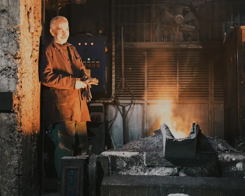
Sand casting is the workhorse process for low-volume hardware production under 500 pieces per year, with tooling cost low enough that one foundry guide treats it as the default for prototyping [S1]. The same process routinely absorbs aluminum, zinc, iron, steel, and bronze alloys, which keeps it on the shortlist for mixed-metal hardware catalogs [S2].
For hardware buyers and process engineers, the 2026 selection question is narrower than the textbook implies: which sand system, which pattern, which tolerance grade, and which ISO 8062 machining allowance fit the part geometry and annual volume. The four gates below cover those decisions without dragging in die-casting economics.
Production volume and tooling life thresholds
Sand casting tooling stays economical for annual volumes up to roughly 1,000-5,000 pieces before die casting undercuts it, and remains viable past 1,000,000 pieces per year for components that other processes reject [S3]. Pattern material drives the upper bound: polyurethane board patterns typically last around 5,000 units, while machined aluminum patterns reach 50,000-100,000 units before rework [S3].
For hardware SKUs that launch below 500 pieces per year and may see design revisions, the low pattern cost and easy modification of PU board or wood patterns is the deciding factor over permanent mold tooling [S1][S3]. The same economics push foundries toward polyurethane and aluminum pattern stock, with wood reserved for one-off prototypes where surface tolerance is secondary.
Sand system comparison: green, resin-bonded, coated, and sodium silicate
Resin-bonded sand, including furan, phenolic, and alkaline phenolic systems, is the mainstream choice when mold accuracy and surface finish outweigh cost, because the binder holds tighter dimensional control and tolerates complex cores [S4]. Green sand (silica + bentonite + water + additives) is the lowest-cost option and dominates high-volume, simpler ferrous hardware such as gray iron, ductile iron, and pipe fittings, but it carries the largest dimensional scatter and the highest risk of moisture-related defects [S4].
Coated or shell sand (silica pre-coated with phenolic resin film) is the pick for thin-walled, high-precision cores in engine blocks, hydraulic valve bodies, and gearboxes, where hot-box or warm-box curing speed and core strength earn the higher resin cost [S4]. Sodium silicate (water glass) sand, hardened by CO2 or self-setting, is the low-toxicity option for steel castings and large thick-walled iron castings, but its poor collapsibility and hygroscopicity limit reuse and can drive white-frost (Na2CO3) defects if the process drifts [S4].
Tolerance, draft, and wall thickness gates under ISO 8062
Modern chemically bonded (dry sand) castings can reach surface finishes in the 1.6 Ra range, with 3.2 Ra and above more typical, against the broader 3.2-25.0 Ra band seen across sand processes [S3]. Achievable linear tolerance sits at +/- 0.4-0.5 mm with an additional 0.2-0.25 mm across parting lines and core joints, while a more typical shop figure is +/- 1 mm plus another +/- 1 mm across the same interfaces [S3].
Draft angles of 1-5 degrees are required on vertical faces, minimum wall thickness is 3 mm for light alloys and 5-6 mm for steel and other ferrous alloys, and maximum wall thickness exceeds 100 mm for heavy sections [S3]. Flatness is held to roughly 0.1 mm per 25 mm excluding localized pitting, and the standard machining allowance is 0.5-1.6 percent, or 1.5-6 mm in absolute terms, set against ISO 8062-3:2007 for castings, ISO 8062-1:2007 for vocabulary, and ISO/TS 8062-2:2013 for the calculation rules [S3]. Hardware drawings that quote tighter than these numbers without negotiated machining stock will fail at the foundry gate.
Pattern and mold-base choices for hardware
Pattern material for sand casting ranges from wood through plastic, rubber, polyurethane board, and machined aluminum, picked by anticipated volume and design-stability risk [S3][S5]. The casting mold is built in two halves packed around the pattern, with runners and gates cut to channel molten metal into the cavity, and cores set into the mold to produce internal cavities and undercuts that the outer mold cannot form [S3][S5].
For hardware that needs internal passages, the sand casting mold approach can produce undercuts, holes, bosses, and protrusions that are uneconomic in permanent mold, because the mold is assembled from multiple pieces and removed from the casting after the metal solidifies [S3]. The mold base hardware, including flask pins, guide bushes, and clamping, is the same family of components that supports both green sand and chemically bonded workflows, so the choice of sand system does not force a retool of the foundry floor.
Limitations, failure modes, and what sand casting cannot do
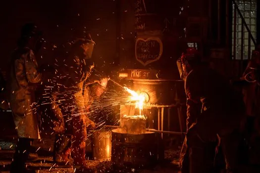
Beach or natural sand cannot be used for metal casting because the natural composition cannot be controlled and the refractory rating falls well short of the 1,000+ °C envelope molten metal imposes [S4]. Green sand's moisture content is the dominant defect source, with pores, sand inclusions, and sand holes showing up when water content drifts outside the binder's working range [S4]. Resin-bonded systems trade that failure mode for fume and odor problems, especially with furan resins, and for a sand-reclamation step that green sand does not need [S4].
Sodium silicate sand, while non-toxic during mixing, suffers from poor collapsibility, hygroscopic strength loss, and white-frost (Na2CO3) efflorescence on casting surfaces if the CO2 curing cycle is not tightly controlled [S4]. Sand casting is also not a tight-tolerance process at the extreme end, and parts that require 1.6 Ra finish, +/- 0.4 mm tolerances, or thin 3 mm walls in light alloys should be confirmed with the foundry before the pattern is cut, because the same geometry may push a competing process such as additive manufacturing material-based mold printing or investment casting into the lead.
When sand casting is the right call, and when it is not
Sand casting is the right call when annual volume stays under 500 pieces, the alloy menu is broad (aluminum, zinc, iron, steel, bronze), geometry includes undercuts or internal passages, and tooling budget is tight [S1][S2][S3]. It is the wrong call when volume clears several thousand pieces per year in a geometry that die casting or investment casting can swallow, when surface finish below 1.6 Ra is mandatory, or when the buyer cannot accept the +/- 1 mm typical tolerance and the associated 0.5-1.6 percent machining stock [S3].
Track these signals before the next hardware SKU goes to bid: the foundry's stated pattern life in units for the chosen pattern material (PU board around 5,000; aluminum 50,000-100,000); the sand system on the foundry's existing reclamation line; the ISO 8062 grade the foundry quotes on its drawing acknowledgement; and the wall-thickness and draft-angle gates above. A drawing that fails any one of those checks is a drawing that will pay for itself to fix on paper rather than on the casting floor.
See also our earlier report, Fire-Rated Door Selection for Data Centers: 2026 Spec Map.