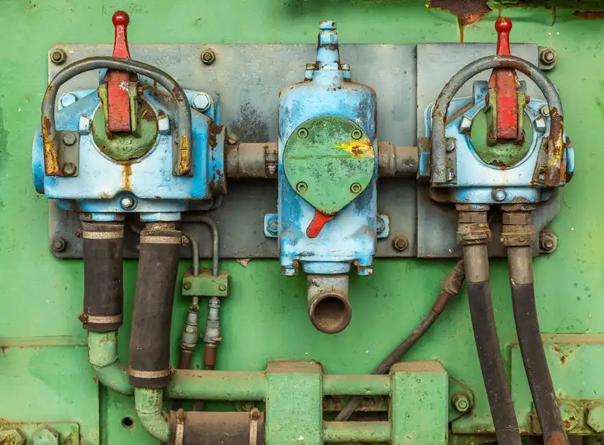
For industrial pump and valve buyers, the practical sand-mold menu is green sand (clay-bonded, reusable), resin-bonded no-bake / air-set sand, and resin shell molds, each matched to a different part size, alloy, and finish envelope [S2][S5].
Ferrous foundries serving this market routinely pour over 100 iron and steel grades, with floor-mold capacity up to 6,000 lb per casting, covering everything from small valve trim to large pump housings [S1]. Sand casting handles steels, stainless steels, cast iron, and non-ferrous alloys in a single foundry, which is why it remains the default for low- and medium-volume pump and valve work [S3].
Green Sand, Resin-Bonded No-Bake, and Shell: What Each Route Actually Delivers
Green sand (silica sand, bentonite clay, moisture, and additives) is the lowest-cost route, supports reusable molds, and remains the default for medium to large valve bodies, pump housings, and engine blocks where surface finish is secondary [S2][S4]. Castings from coarse green sand carry a rough surface and tighter dimensional spread, but the loop economics (sand reclaimed after compensating lost moisture and additives) keep unit cost down on long runs [S4].
Resin-bonded no-bake / air-set sand (sand plus a fast-curing adhesive) is the workhorse for complex pump and valve geometries and for stainless or nickel-bearing alloys, because the cured mold is dimensionally stable and produces smoother castings than green sand at the cost of a one-shot mold [S2][S4][S5]. Resin shell molding, an evolution of the same chemistry, suits intricate and detailed patterns, tolerates thin walls and fine internal passages, and is the higher-cost option in the family [S5].
Decision Matrix: Molding Route vs. Part, Alloy, and Volume
Volume and part size sort the routes first. Green sand is favored for high volume and large ferrous castings (engine blocks, valve bodies, pump casings) where the rough surface is acceptable and the per-mold cost must be minimal [S2][S4]. Resin no-bake is the default for low- to medium-volume, complex, or alloy-sensitive parts such as stainless steel pump impellers and corrosion-resistant valve bodies, where the smoother surface and lower defect rate offset the disposable-mold cost [S3][S5].
Alloy and finish sort them next. Sand as a category handles ferrous and non-ferrous alloys (iron, carbon and stainless steel, aluminum, brass, bronze, magnesium) and high-melting-point metals such as titanium and nickel-base alloys that would attack permanent tooling [S2][S4]. For impellers, where surface finish drives hydraulic efficiency, sand casting competes with investment casting routes: sand wins on cost, section size, and alloy flexibility, while investment casting wins on as-cast surface, tolerance, and finer vane detail [S6].
Geometry and lead time sort the rest. Dry sand / no-bake molds enable complex internal passages via sand cores and cope-and-drag assembly, making them the default for valve bodies with intersecting bores [S2][S4]. For prototypes, low-volume, or replacement of complicated core assemblies, additively printed sand molds and cores are now a routine option, replacing multi-core stacks with a single printed core and shortening lead time [S4].
Sand and Binder Selection: Silica, Olivine, Chromite, Zircon, and Resin Chemistry
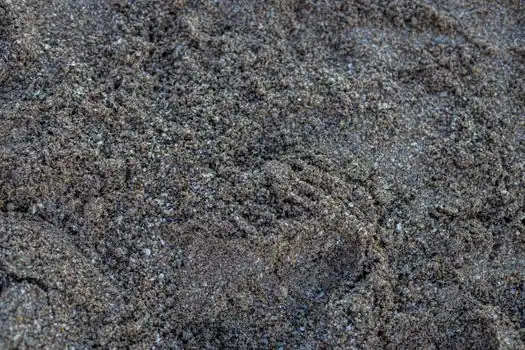
Base sand choice is governed by reusability, refractoriness, permeability, and grain size; silica sand is the default, with olivine, chromite, zircon, and chamotte selected for higher-temperature or specialty alloys [S2]. The binder is the chemistry that holds the system together: clay and water (green sand), oil, cured resin, or sodium silicate, with additives tuning green strength, collapsibility, venting, and cushioning [S2].
Resin-bonded systems (phenolic, furan, or urethane no-bake) yield higher strength and better surface than green sand, which is why they dominate stainless and alloy pump and valve work, while sodium silicate routes are used where lower emissions or a different breakdown profile are specified [S2][S5]. The trade-off is direct: more binder and more refractory base sand raise mold cost but cut defect rates, particularly shrinkage porosity and misruns in thin-wall valve trim and impeller vanes [S2][S7].
Defect Modes the Selection Has to Defend Against
Porosity, shrinkage cavities, misruns, sand inclusions, and surface roughness are the five defect signatures that drive every sand-system decision for pump and valve work, and each maps to a specific process control [S2][S4][S7]. Numerical simulation of stainless steel pump impeller sand castings, for example, isolates shrinkage and gas porosity as the dominant failure modes, and links them to runner design, pouring temperature, and the placement of sand cores feeding the hub [S7].
Pouring path and gating matter as much as the sand itself: a well-designed sprue and runner system delivers metal to the cavity free of oxides and inclusions, while a poorly vented cope produces misruns on thin vane tips [S2][S4]. For pump and valve castings that will later be machined to a sealing surface, the additional machining allowance built into the pattern directly offsets the rough as-cast surface typical of green sand [S4].
Standards, Sourcing, and Foundry Qualification
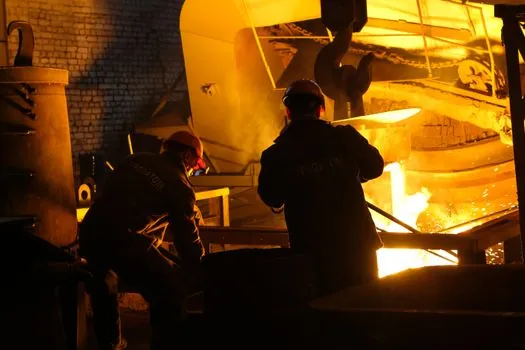
For pressure-containing valve bodies and pump casings, the casting specification is rarely "sand" alone; it is a material standard (ASTM A216 for carbon-steel valve castings, A351 for stainless, A48 / A536 for iron grades) plus a quality clause that ties down hardness, radiographic acceptance, and NDE scope. Material availability is a real constraint: ferrous sand foundries that ship into the pump and valve OEM base typically run more than 100 iron and steel grades, including proprietary alloys, with on-site metallurgical support for grade selection [S1].
Tooling economics also drive the decision. Sand as a mold material keeps pattern and tooling cost low compared with permanent mold or die casting, because the mold is destroyed and a new sand mold is made from the reusable pattern each cycle; this is the structural reason sand is the default for low-volume and custom pump and valve designs [S2][S4][S8]. For related selection logic on the broader casting mold family and on the mold base supporting the cope and drag, the encyclopedia pages track the same pattern-versus-permanent cost trade-off that shows up here.
Practical next node: pull three foundry quotes for the same pump housing drawing, one green sand, one no-bake, one shell or investment, with a stated ASTM grade, hardness cap, radiographic acceptance level, and pattern cost, and compare total landed cost against the as-cast surface the downstream machining budget can absorb. Trackable signal to monitor over the next two quarters: continued substitution of additively printed sand cores for multi-core assemblies in complex valve bodies, and wider use of simulation-driven gating to cut shrinkage scrap in stainless pump impellers [S4][S7]. For adjacent reading, the die selection logic for telecom enclosure castings applies the same alloy-and-cavity trade-off to a different end market, while the mold and die gas selection guide covers the nitrogen and argon envelopes that protect molten pours in these same foundries.