
Foundry sand mixers blend bentonite, water, returning sand, and additives into a homogeneous molding mix, with production units commonly processing 5–80 t/h on cycles of 3–8 minutes depending on rotor geometry and binder system [S1].
Selection hinges on four variables: sand type (green sand, resin-coated, no-bake), batch vs. continuous topology, m³/h throughput, and the abrasive wear budget allocated to shaft seals, blades, and the muller bottom. A wrong match shows up as moisture variance over ±1.0%, muller dead zones, or scrap rates above the 2–4% foundry benchmark [S2].
Core Working Principle and Configuration Classes
A sand mixer is a mechanical mulling device: a horizontal or vertical pan holds the sand mass while counter-rotating rotors (or a wheel/roller in wheel-type units) shear and knead bentonite into the silica grain surface. Vertical wheel mixers typically run at 30–60 rpm wheel speed with rotor-tip velocities in the 8–14 m/s band; horizontal-shaft batch units push mulling energy at 5–12 kWh per tonne of sand. Continuous power mixer topologies feed sand and binder on a controlled mass-flow basis and discharge a steady-state mix, removing the per-batch reset overhead of a batch wheel.
Three configurations dominate foundry floors. (1) Wheel (vertical) mixers for green-sand preparation at 30–120 t/h, used behind a sand cooler and before a mold line. (2) Horizontal-shaft rotor batch mixers for resin-coated sand (shell, hot-box, cold-box binder stages) at 5–25 t/h, where the resin sand line calls for shorter residence time and lower mulling intensity. (3) Continuous power mixer units for no-bake furan/PHENOLIC lines, where steady-state discharge directly feeds a flask-fill station.
Measured Advantages on the Foundry Floor
Mulling delivers a uniform moisture envelope — properly tuned wheel mixers hold green-sand moisture within ±0.3% of the setpoint, against ±1.0% or worse on under-powered rotor-only units [S1]. The same mulling action activates bentonite's smectite platelets: a 3–6 minute wet-mull cycle lifts the wet tensile strength of a 6% bentonite mix to the 30–50 kPa range needed for high-pressure flask molding. Energy per tonne processed sits in the 5–12 kWh/t band for wheel units, lower per-tonne than pneumatic or hand-mulled alternatives.
Operational gains scale with throughput. Continuous sand mixer designs cut per-batch dead time (loading + discharge) from 60–90 s down to a near-zero steady-state, raising effective m³/h on the same motor base. Mixer-integrated control platforms now expose Modbus/TCP and PROFINET, so the same PLC node reads amp draw, water flow, and discharge moisture in one register set.
Measured Disadvantages and Failure Modes
The four recurring pain points are shaft-seal wear, dead zones in the pan, energy draw, and cleanup time. Abrasive silica plus 4–6% moisture cuts lip-seel life on horizontal rotors to 3–9 months in high-tonnage green-sand duty; once a seal leaks, bentonite-laden slurry wrecks the bearing housing. Vertical wheel units avoid the shaft-seal problem but substitute a muller-tire wear issue — wheel-rail contact surfaces need re-machining or hard-facing every 12–24 months in two-shift operation. Pan corners and the area under the plow blade are classic dead-zone locations: sand that stalls there loses moisture control and shows up as lumps in the discharge. [S1]
Energy and housekeeping carry a real cost. A 60 t/h wheel mixer can draw 80–160 kW continuously, and that draw scales roughly linearly with sand weight, not with binder quality. Cleanup between binder changes (green-sand to resin, or furan to phenolic) on a single unit can consume 4–8 hours of operator time plus 200–600 L of wash water, which is why dual-line foundries often run two mixers instead of one shared unit. Noise routinely sits at 85–95 dBA at the operator station, putting the unit inside the OSHA 29 CFR 1910.95 hearing-conservation threshold at 85 dBA TWA8.
Decision Matrix: Which Mixer Class Fits Which Job
Buyers can line up the three main classes against four decision criteria: throughput (m³/h), binder compatibility, maintenance access, and footprint.
Selection logic: green-sand flask/mold lines with a dedicated sand cooler upstream almost always justify a vertical wheel unit for the 30–120 t/h bracket, accepting the rail-maintenance interval. Jobbing foundries running 5–15 t/h of varied resin systems fit a horizontal rotor batch unit, where the shorter changeover and seal-swap access pay back faster than steady-state efficiency. Continuous resin lines feeding a high-pressure flask station fit a continuous sand mixer head with mass-flow-controlled binder dosing, but only when return-sand temperature is already controlled below 35 °C by a sand cooler — hot return sand kills resin cure.
Comparison: Wheel, Horizontal-Batch, and Continuous Topologies
Wheel (vertical) units lead on green-sand moisture uniformity and energy per tonne, but trail on seal-free operation and corner-cleanout access. Horizontal-shaft batch rotors lead on binder flexibility and seal replacement time, with the trade-off of batch dead time and higher per-tonne energy. Continuous power mixer units lead on steady-state throughput and PLC integration, but they punish any upstream moisture or temperature excursion — the same steady-state assumes stable feed. A useful rule of thumb on green-sand lines: 1 kW of installed rotor power reliably processes 0.5–1.0 t/h, so a 100 t/h line budgets 50–100 kW of mulling motor base plus 30–50% for hydraulic plow drives, water pumps, and dust hood extraction. [S2]
Limits and What the Equipment Will Not Do
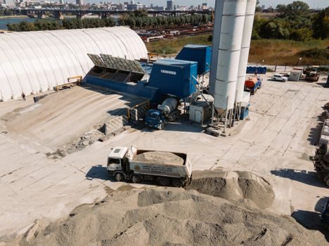
Three constraints define the envelope. (1) A sand mixer does not cool sand — the discharge temperature tracks the inlet, and a sand cooler or fluidized-bed cooler must precede it for return-sand loops above 60 °C. (2) A mixer does not classify — tramp metal, lumps above 50 mm, and foreign debris upstream will jam the plow and crack a muller-tire in wheel units. (3) A mixer does not fix a bad sand system: bentonite quality, water hardness, and return-sand aeration set the ceiling on moisture control, and mulling energy cannot push a poor-quality bentonite into the 30–50 kPa wet-tensile band. A foundry running over 150 t/h of return sand on green-sand molding typically also spec a concrete mixer truck for sand-handling infeed, since auger or sand blasting machine feed hoppers alone cannot sustain that mass flow. [S2]
Sourcing and Standards Watch

Spec sheets worth pulling when comparing bids: motor nameplate kW and service factor (typically 1.15 for foundry duty per NEMA MG-1), rotor tip speed (8–14 m/s for green-sand wheel units), seal material (typically NBR or HNBR for aqueous bentonite, FKM for resin service), plowing horsepower, discharge gate cycle time, and PLC protocol list. A standard for foundry sand system testing — including the AFS 2200-series moulding sand test methods for moisture, permeability, and green compression — should be cited in the FAT document so the moisture and tensile numbers are comparable across bids. ATEX 2014/34/EU zone-20 inside the pan and zone-21 around the hood apply to any unit handling a combustible dust atmosphere; IEC 60079-0 / IEC 60079-31 govern the dust-ignition-proof motor and panel choices on European builds. The same sand system is the upstream feed for a sand blasting machine when the foundry runs its own surface-prep cells. [S2]
Track these two signals over the next buying cycle: (a) motor nameplate kW and rotor-tip-velocity bands quoted on tender documents — units below 5 kWh/t for green-sand wheel duty usually mean under-driven rotors that will fail moisture uniformity. (b) seal and rail maintenance interval in published MTBF claims — a 3–9 month seal interval on horizontal rotors and a 12–24 month rail-re-machining interval on vertical wheels are the realistic baseline for two-shift green-sand service. Cross-reference to the coding machine total-cost map and the core making machine classifications for the broader plant layout, since mixer, core-making, and coding cells sit on the same return-sand loop.